Laser driving device, laser driving method, optical unit, and light device

Inactive Publication Date: 2010-10-14
SONY CORP
View PDF8 Cites 5 Cited by
  • Summary
  • Abstract
  • Description
  • Claims
  • Application Information

AI Technical Summary

Benefits of technology

[0015]According to a form of the present invention, there are a small number of kinds of signals being transmitted, so that the problems of the number of transmissions and a reduction in transmission band are solved. This is because the problem caused by a length for securing a signal line arrangement space and routing is alleviated.

Problems solved by technology

At this time, a transmission band is limited by the flexible board, and intervals of the light emission timing signal cannot be transmitted accurately, which hinders improvement in recording speed.
Further, a write strategy tends to become complex toward achievement of high-density and high-speed recording.
With the existing configuration, as the number of power levels is increased, the number of lines for laser driving control is increased, the flexible board (width of the flexible board) becomes larger, and a problem of a reduction in transmission band which problem is caused by a length for securing an arrangement space and routing occurs.
When the light emission power of a laser is controlled, there occurs another problem of how to transmit a feedback signal and a sampling pulse for controlling the light emission power.

Method used


Image

  • Laser driving device, laser driving method, optical unit, and light device
  • Laser driving device, laser driving method, optical unit, and light device
  • Laser driving device, laser driving method, optical unit, and light device

Examples


first embodiment (

5. First Embodiment (Independent Power Level Change for Spaces and Marks)

second embodiment (

6. Second Embodiment (Sampling Pulse Setting Change: Independent of Power Level Change)

[0059]7. Third Embodiment (Sampling Pulse Setting Change: Interlocked with Power Level Change / Superimposition of Only Start Timing on Edge Signal)

fourth embodiment (

8. Fourth Embodiment (Sampling Pulse Setting Change: Interlocked with Power Level Change / Superimposition of Start and End Timing on Edge Signal)

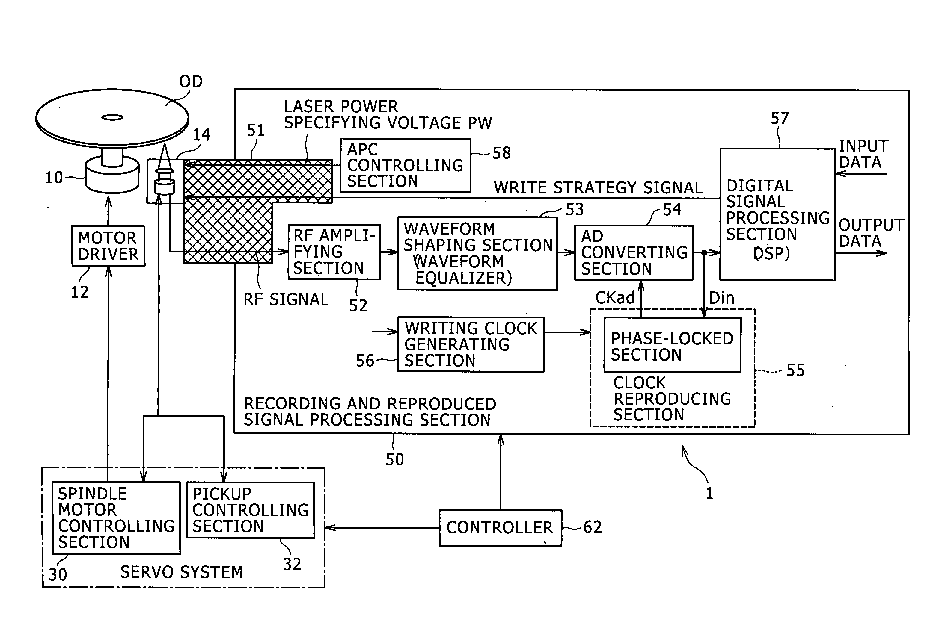
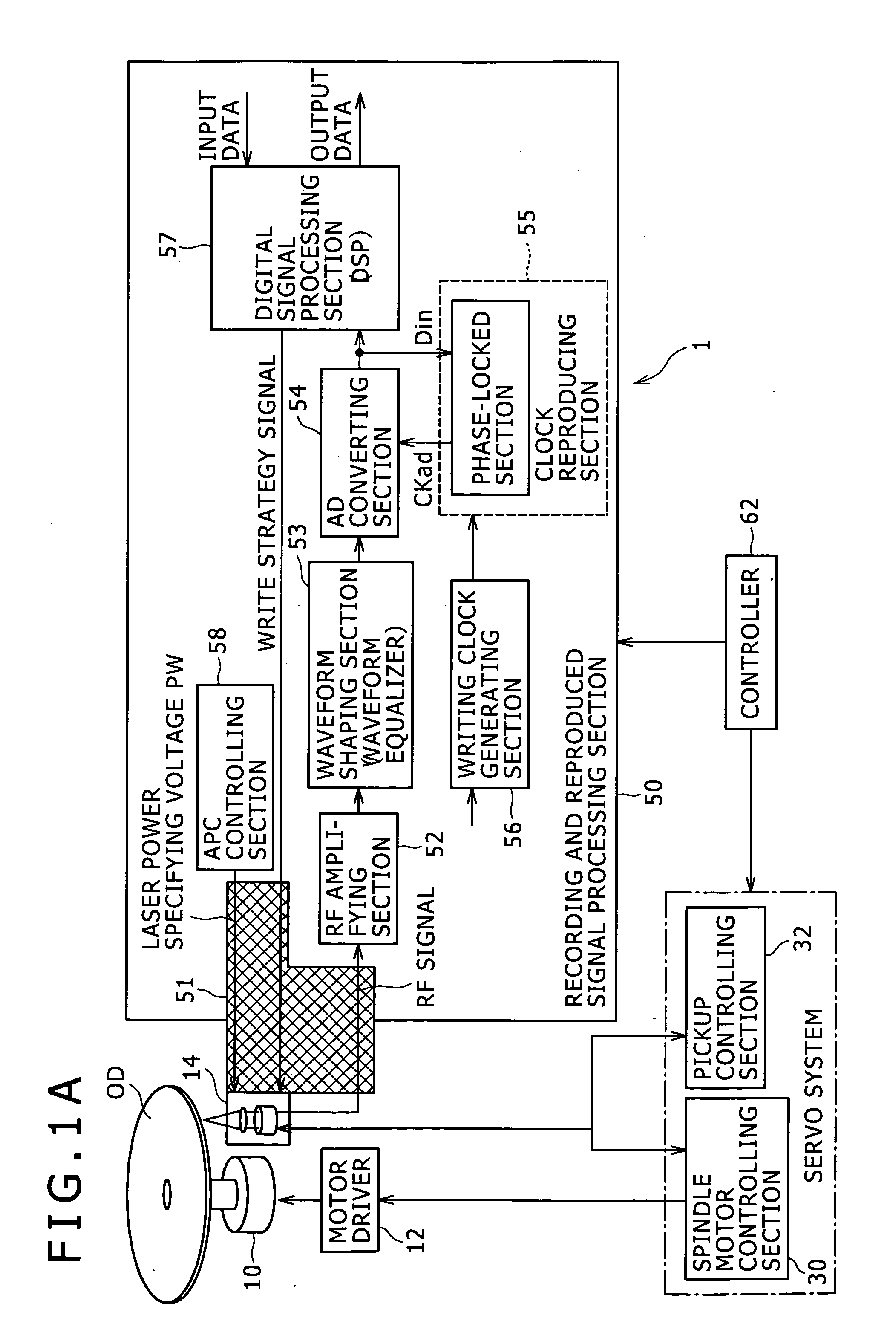
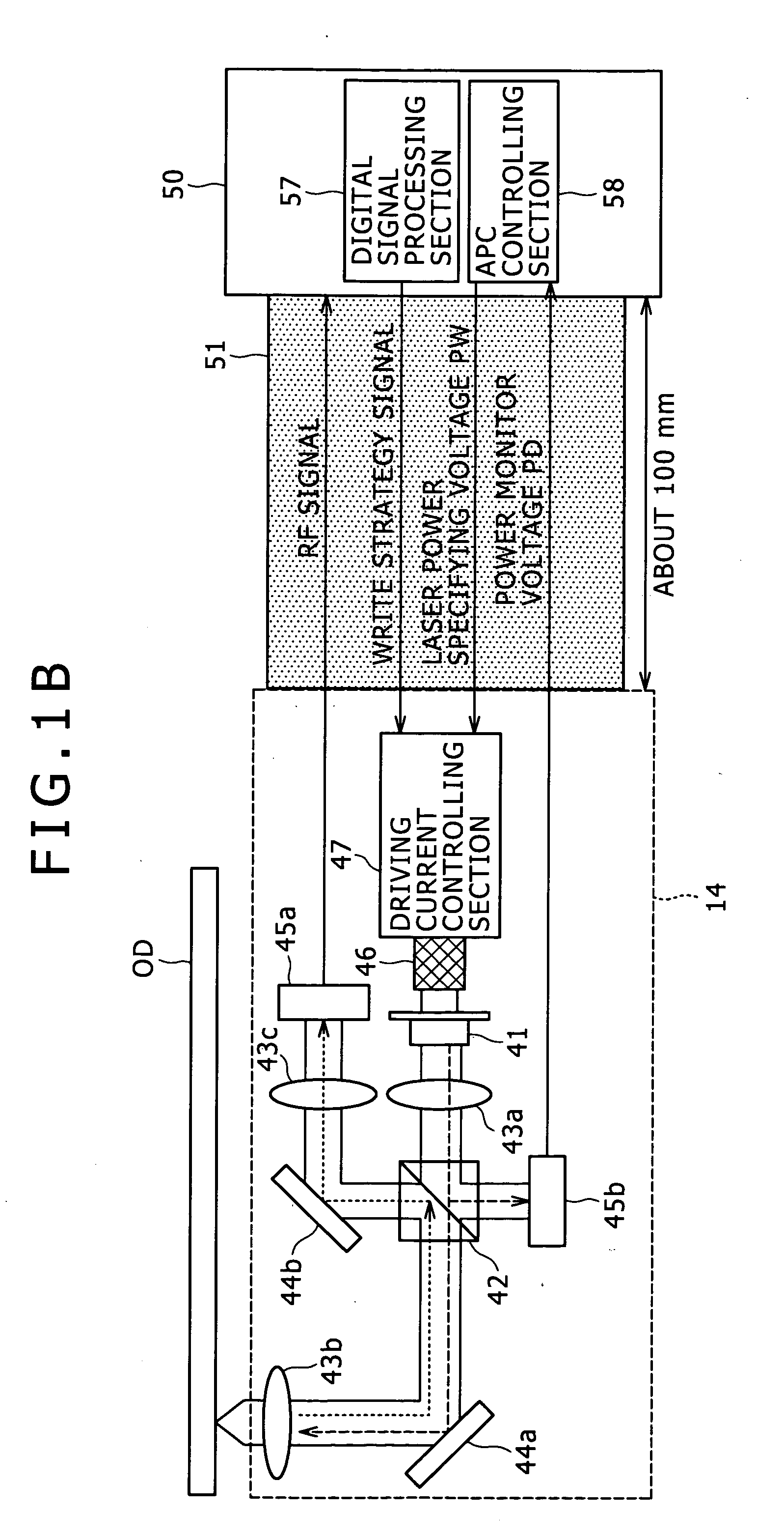
[0060]FIG. 1A is a diagram showing an example of configuration of a recording and reproducing device (optical disk device) as an example of an optical device. FIG. 1B is a diagram of assistance in explaining an example of configuration of an optical pickup.

[0061]An optical disk OD may be not only a so-called reproduction-only optical disk such as a CD (Compact Disk), a CD-ROM (Read Only Memory), or the like but also for example a write-once optical disk such as a CD-R (Recordable) or the like or a rewritable optical disk such as a CD-RW (Rewritable) or the like. Further, the optical disk is not limited to CD-type optical disks, but may be an MO (magneto-optical disk), an ordinary DVD (Digital Video or Versatile Disk), or a DVD-type optical disk such as a next-generation DVD using a blue laser having a wavelength of about 405 nm, for example....


PUM


Abstract

A laser driving device includes: a first pulse generating section; a second pulse generating section; a light emission waveform generating section; and a light emission level pattern storing section.

Description

BACKGROUND OF THE INVENTION[0001]1. Field of the Invention[0002]The present invention relates to a laser driving device (laser driving circuit), a laser driving method, an optical unit, and a light device.[0003]2. Description of the Related Art[0004]Recording and reproducing devices using a laser as a light source are used in various fields. For example, attention is directed to optical disk recording and reproducing devices (hereinafter referred to simply as optical disk devices) using a laser driving device and an optical unit and using an optical disk as a recording and reproducing medium. As the laser used as light source, semiconductor lasers using semiconductor materials have recently been widely used in various devices because the semiconductor lasers are very small and respond to driving current at high speed.[0005]As a writable optical disk used as a recording and reproducing medium, a phase change optical disk, a magneto-optical disk and the like are widely known. Recordin...

Claims


Application Information

Patent Timeline
IPC IPC(8): G11B7/00
CPCG11B7/0062H01S5/06835H01S5/0428G11B7/1263
Inventor KURIHARA, TSUTOMUKIMURA, MOTOIYOKOYAMA, KOICHI
Owner SONY CORP
Why Eureka
Try Eureka