Shift register of LCD devices

a technology of shift register and lcd device, applied in the field of shift register, can solve the problems of power consumption and eventual failure of pull-down operation, and achieve the effect of reducing the power consumption

Active Publication Date: 2010-10-14
AU OPTRONICS CORP
View PDF11 Cites 141 Cited by
  • Summary
  • Abstract
  • Description
  • Claims
  • Application Information

AI Technical Summary

Problems solved by technology

The clock signals CH1 and CH2 need to have higher frequencies, and power consumption also increases accordingly.
In addition to high power consumption, the pull-down operation might eventually fail as the characteristics of the transistor switches deviate with time.

Method used


Image

  • Shift register of LCD devices
  • Shift register of LCD devices
  • Shift register of LCD devices

Examples


Embodiment Construction

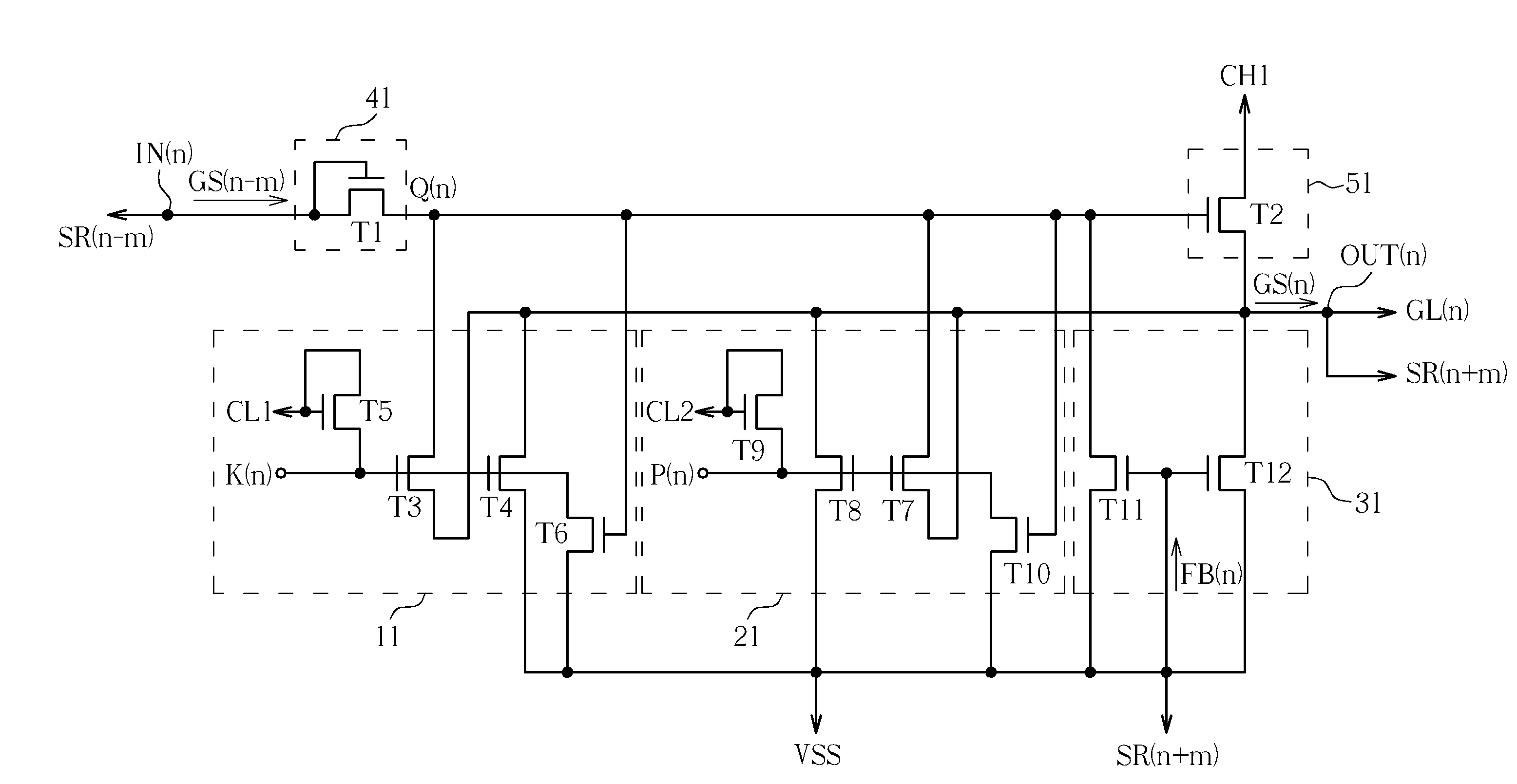
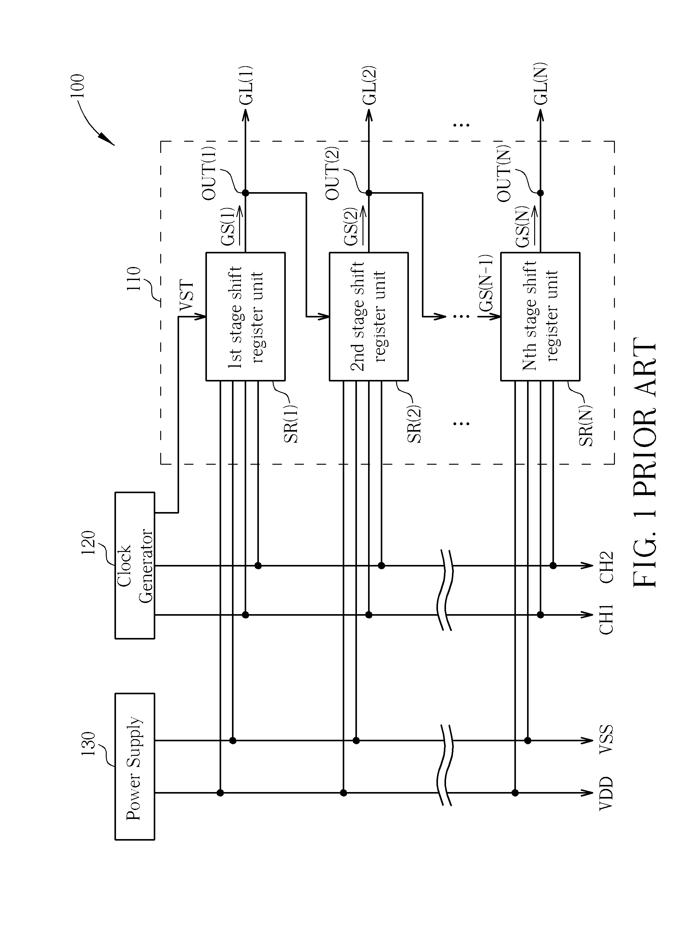
[0028]Referring to FIGS. 5 and 6, which depict simplified functional diagrams of an LCD device 300 according to the present invention, including gate lines GL(1)-GL(N), a shift register 210, a clock generator 220 and a power supply 230. For operating the shift register 210, the clock generator 220 provides start pulse signals VST / VST1 / VST2, a plurality of high-frequency clock signals CH1-CHM, and two low-frequency clock signals CL1 and CL2, while the power supply 230 provides a bias voltage VSS. The shift register 210 includes a plurality of serially-coupled shift register units SR(1)-SR(N). According to corresponding high-frequency clock signals CH1-CHM, corresponding input signals ST(1)-ST(N−1) and corresponding feedback signals FB(1)-FB(N), the shift register units SR(1)-SR(N) can sequentially output gate driving signals GS(1)-GS(N) to the corresponding gate lines GL(1)-GL(N) at respective output ends OUT(1)-OUT(N). For the 1st stage shift register unit SR(1), the input signal ST...


PUM


Abstract

A shift register includes a plurality of shift register units coupled in series. Each shift register unit, receiving an input voltage at an input end and an output voltage at an output end, includes a node, a pull-up driving circuit, a pull-up circuit and first through third pull-down circuits. The pull-up driving circuit can transmit the input voltage to the node, and the pull-up circuit can provide the output voltage based on a high-frequency clock signal and the input signal. The first pull-down circuit can provide a bias voltage at the node or at the output end based on a first low-frequency clock signal. The second pull-down circuit can provide a bias voltage at the node or at the output end based on a second low-frequency clock signal. The third pull-down circuit can provide a bias voltage at the node or at the output end based on a feedback voltage.

Description

BACKGROUND OF THE INVENTION[0001]1. Field of the Invention[0002]The present invention is related to a shift register, and more particularly, to a shift register which drives pull-down circuits using low-frequency signals.[0003]2. Description of the Prior Art[0004]Liquid crystal display (LCD) devices, characterized in low radiation, small size and low power consumption, have gradually replaced traditional cathode ray tube (CRT) devices and been widely used in various electronic devices, such as notebook computers, personal digital assistants (PDAs), flat panel televisions or mobiles phones. Traditional LCD devices display images by driving the panel pixels using external driver chips. In order to reduce the number of devices and manufacturing costs, GOA (gate driver on array) technique has been developed in which the gate driver is directly manufactured on the LCD panel. A GOA gate driver usually functions in form of shift register, in which pull-up circuits provide a plurality of ga...

Claims


Application Information

Patent Timeline
Patent Type & Authority Applications(United States)
IPC IPC(8): G11C19/00
CPCG09G3/3677G09G2300/0408G11C19/00G09G2320/0219G11C19/28G09G2310/0286
Inventor TSAI, TSUNG-TINGLAI, MING-SHENGCHIANG, MIN-FENGLIU, CHUN-HSIN
Owner AU OPTRONICS CORP
Why Eureka
Try Eureka