
Method and apparatus for using a vertical furnace to infuse carbon nanotubes to fiber

a carbon nanotube and furnace technology, applied in the field of system, method and apparatus for the continuous synthesis of carbon nanotubes, can solve the problems of affecting the mechanical properties of glass fibers such as “e-glass,” degrading significantly, and further problems down the process lin

Inactive Publication Date: 2010-10-14
APPL NANOSTRUCTURED SOLUTIONS LLC
View PDF103 Cites 35 Cited by
  • Summary
  • Abstract
  • Description
  • Claims
  • Application Information

AI Technical Summary

Problems solved by technology

Generally, conventional CNT synthesis has required high temperatures in the range of 700° C. to 1500° C. However, many fibers and sizings on which CNTs are to be formed are adversely affected by the high temperatures generally required for CNT synthesis in conventional processes.
For example, at such relatively higher temperatures, the mechanical properties of a glass fiber, such as “E-glass,” degrade significantly.
These losses can propagate and cause further problems down the process line as deteriorated fibers can fray and break under tension and in low-radius turns.
Other fibers including carbon fibers can experience similar problems.

Method used


Image

  • Method and apparatus for using a vertical furnace to infuse carbon nanotubes to fiber
  • Method and apparatus for using a vertical furnace to infuse carbon nanotubes to fiber
  • Method and apparatus for using a vertical furnace to infuse carbon nanotubes to fiber

Examples


example 1

[0055]This prophetic example shows how a carbon fiber material can be infused with CNTs in a continuous process utilizing an embodiment of the vertical furnace.

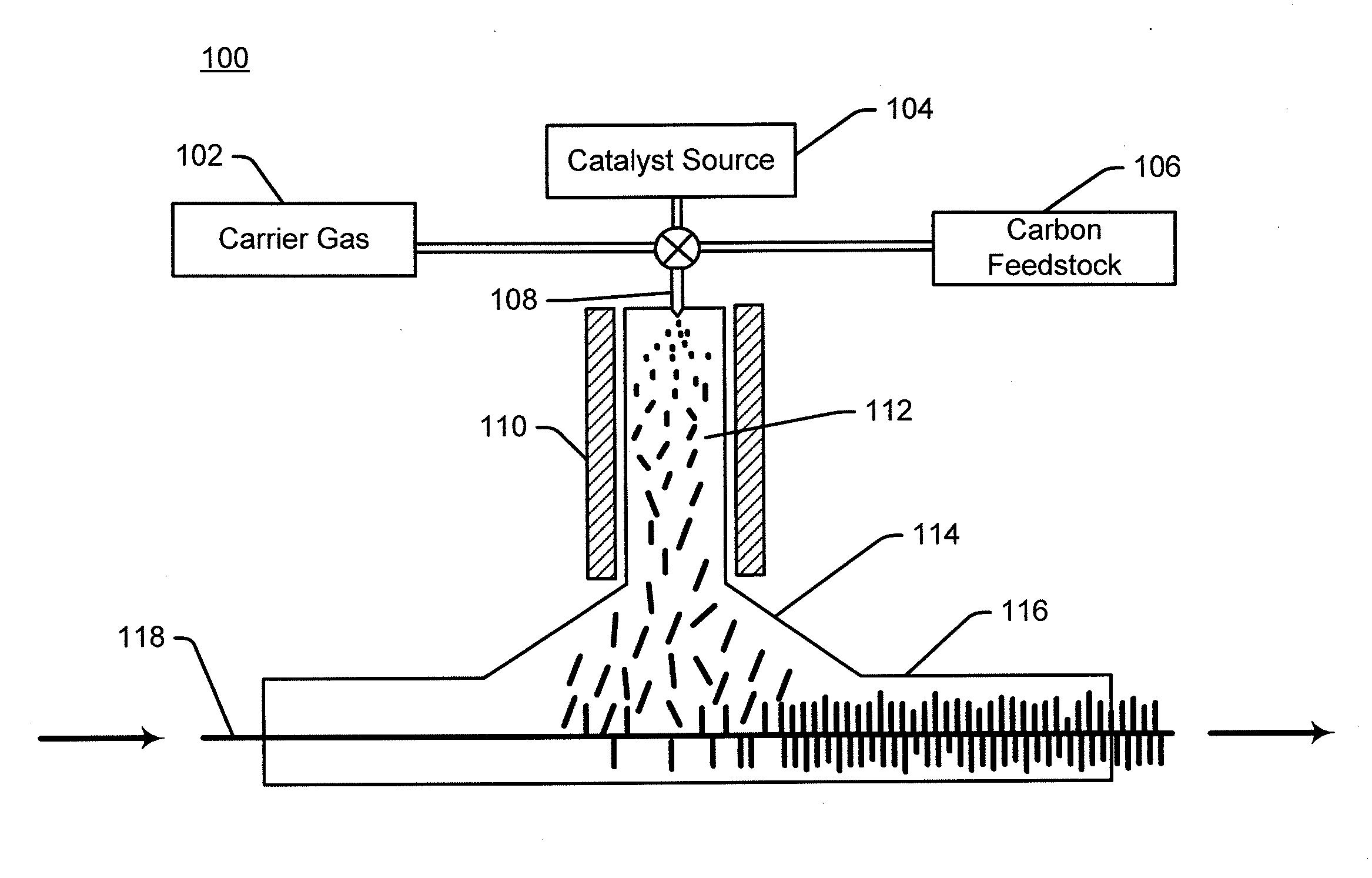
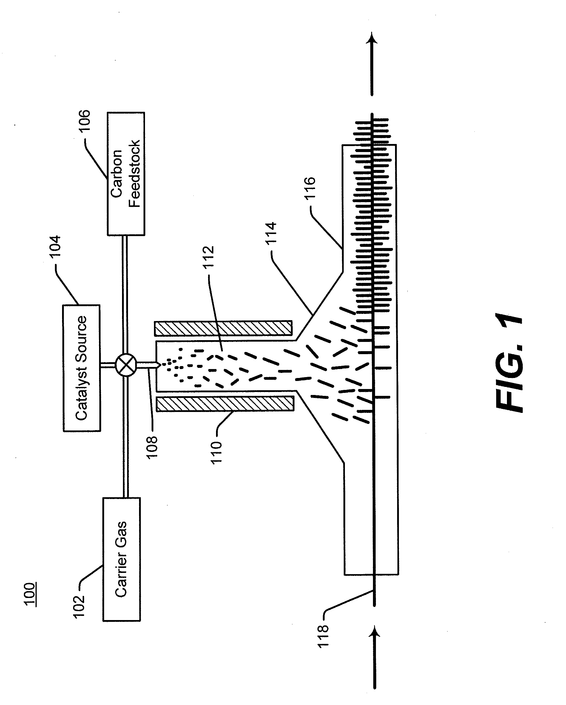
[0056]FIG. 1 depicts system 100 for producing CNT-infused fiber in accordance with the illustrative embodiment of the present invention. System 100 includes a catalyst source 104, carbon feedstock source 106, and carrier gas source 102, CNT growth zone 112, gas / vapor inlet device 108, a heating element 110, a dispersion hood 114, an infusion chamber 116, a plasma system (not illustrated), and a carbon fiber substrate 118.

[0057]Carrier gas source 102 provides a flow of nitrogen gas at a rate of about 60 liters / minute, which mixes with acetylene gas from the carbon feedstock source 106 supplied at a rate of about 1.2 liters / minute. The nitrogen / acetylene gas mixture is used as the atomizing gas in a nebulizer spray system, gas / vapor inlet device 108, where a 1% mass iron acetate solution in isopropyl alcohol is used as the cata...


PUM

PropertyMeasurementUnit
temperatureaaaaaaaaaa
temperaturesaaaaaaaaaa

Abstract

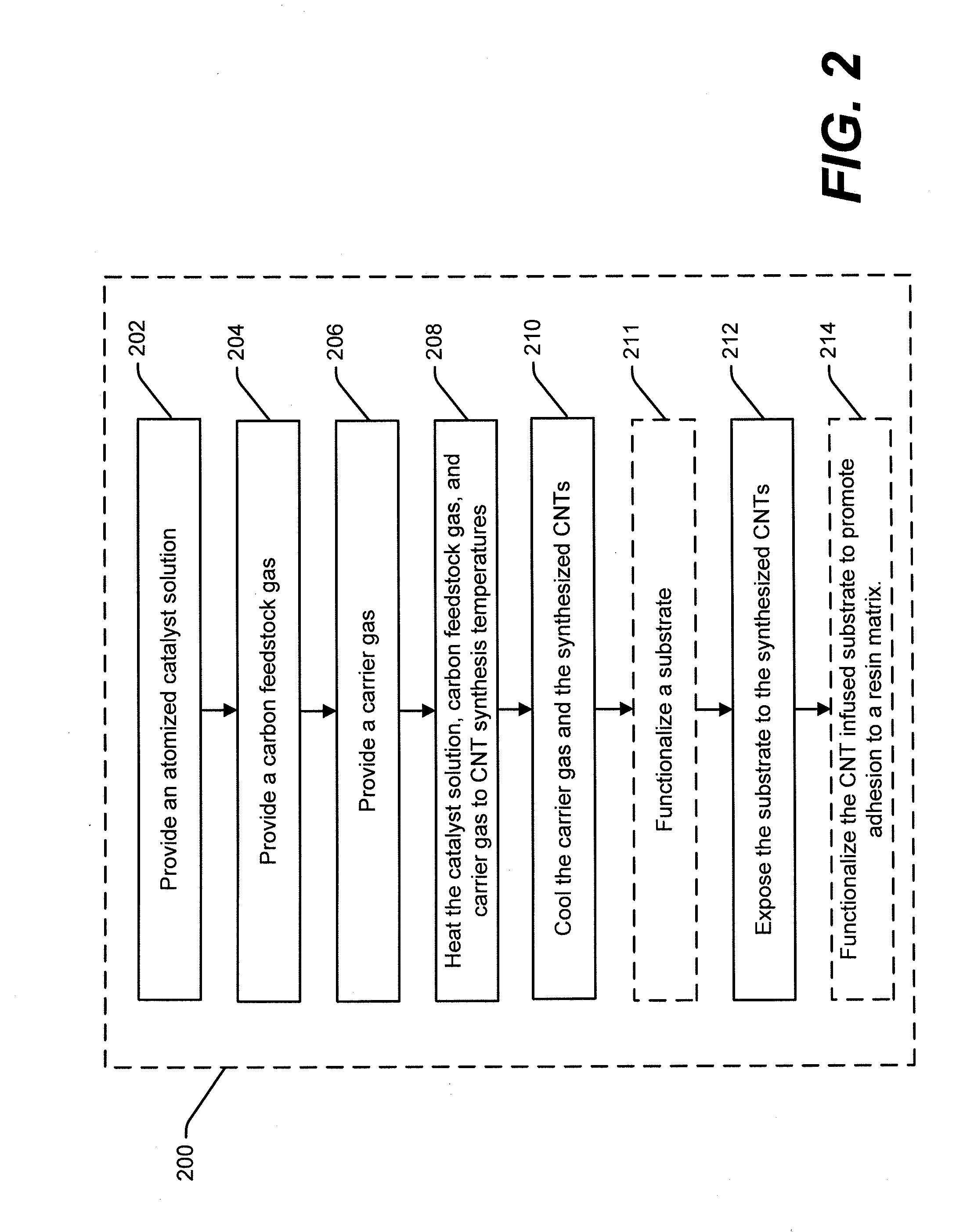
A method for forming a CNT infused substrate comprises exposing a catalyst nanoparticle, a carbon feedstock gas, and a carrier gas to a CNT synthesis temperature, allowing a CNT to form on the catalyst nanoparticle, cooling the CNT, and exposing the cooled CNT to a surface of a substrate to form a CNT infused substrate.

Description

STATEMENT OF RELATED APPLICATIONS[0001]This application claims priority to U.S. Provisional Application No. 61 / 168,526, filed on Apr. 10, 2009, which is incorporated herein by reference in its entirety.STATEMENT REGARDING FEDERALLY SPONSORED RESEARCH OR DEVELOPMENT[0002]Not applicable.FIELD OF THE INVENTION[0003]The present invention relates in general to a system, method and apparatus for the continuous synthesis of carbon nanotubes.BACKGROUND OF THE INVENTION[0004]Fibers are used for many different applications in a wide variety of industries, such as the commercial aviation, recreation, industrial and transportation industries. Carbon nanotubes (“CNTs”) exhibit impressive physical properties such as exhibiting roughly eighty times the strength, six times the stiffness (i.e., Young's Modulus), and one-sixth the density of high carbon steel. CNTs can be useful when integrated into certain fibrous materials such as composite materials. Hence, developing CNTs within composite materia...

Claims


Application Information

Patent Timeline
Patent Type & Authority Applications(United States)
IPC IPC(8): B05D1/00C23C16/00
CPCB82Y30/00D06M11/74C01B31/024B82Y40/00C01B32/164D06M11/73
Inventor MALECKI, HARRY C.SHAH, TUSHAR K.ALBERDING, MARK R.
Owner APPL NANOSTRUCTURED SOLUTIONS LLC
Learn More