

Ignition device for internal combustion engine
a technology for internal combustion engines and ignition devices, which is applied in the direction of ignition safety means, automatic control of ignition, machines/engines, etc., and can solve problems such as the possibility of releasing the lock
- Summary
- Abstract
- Description
- Claims
- Application Information
AI Technical Summary
Benefits of technology
Problems solved by technology
Method used
Image

Examples
first embodiment
[0037](First Embodiment)
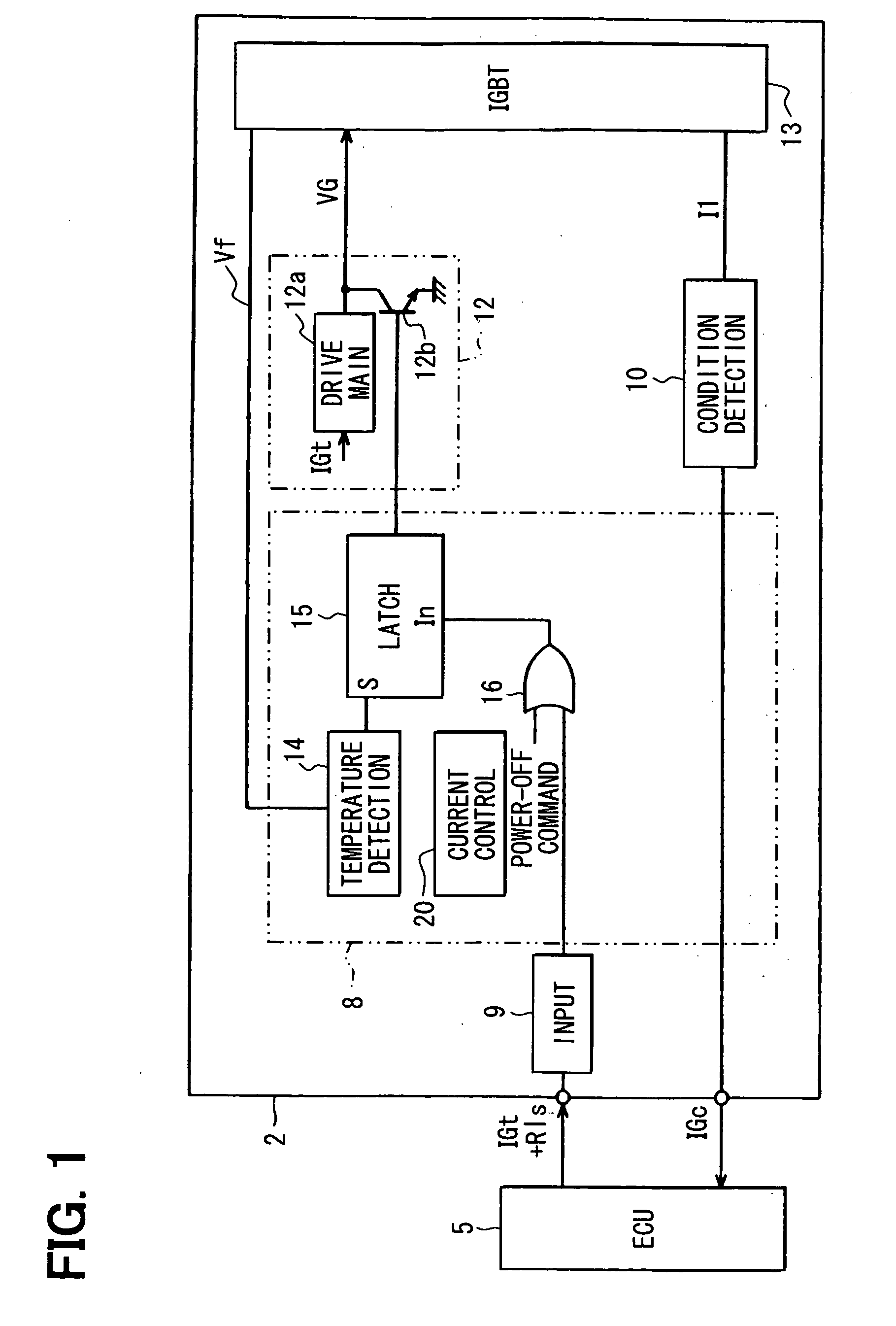
[0038]The first embodiment of the present invention will be described with reference FIGS. 1 to 7, in which an ignition device for an internal combustion engine is shown generally in a block diagram and denoted by a reference numeral 1.
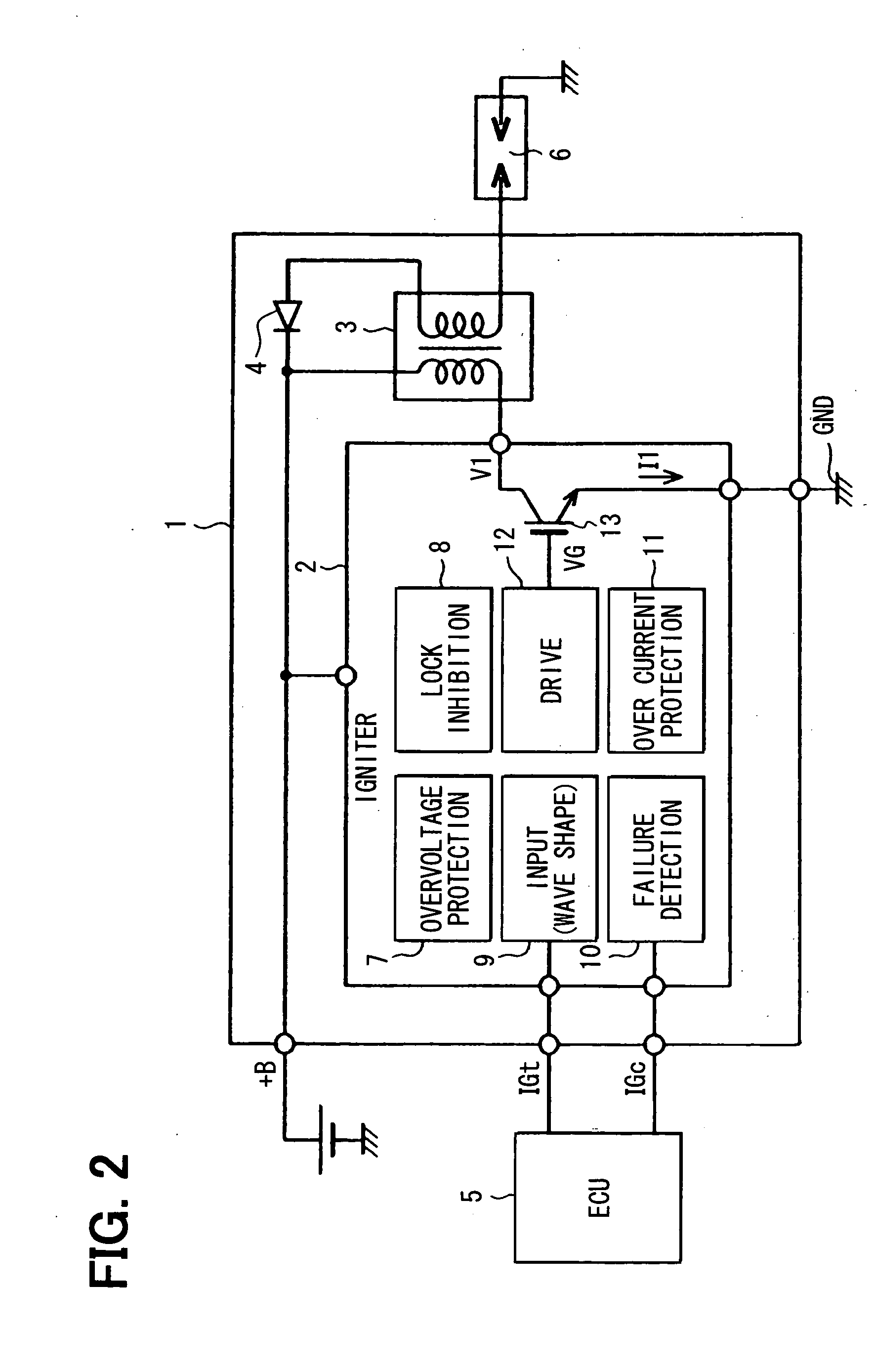
[0039]As shown in FIG. 2, the ignition device 1 is provided with an igniter 2, an ignition coil 3, a diode 4 and the like to operate with a power supply voltage of a battery +B. The ignition device 1 is configured to activate a spark plug 6 through the ignition coil 3 in response to an ignition signal IGt produced from an electronic control unit (ECU) 5 so that fuel may be ignited by ignition spark generated by the spark plug 6.
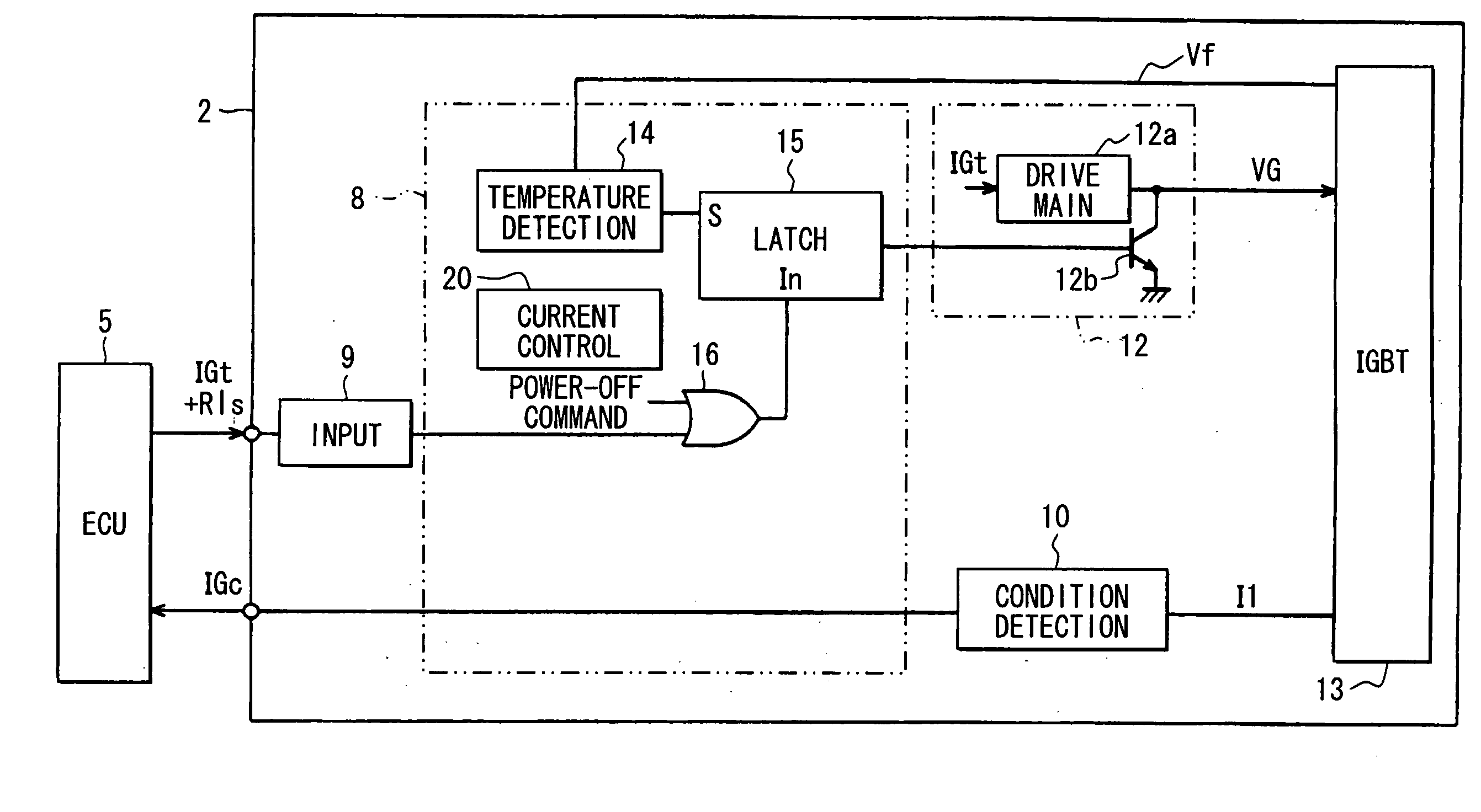
[0040]The igniter 2 is mainly provided with an over-voltage inhibition circuit 7, a lock inhibition circuit 8, an input circuit (waveform shape circuit) 9, a condition detection circuit 10, an over-current protection circuit 11 and a drive circuit 12. An insulated gate bipolar transistor (IGBT) 13 is con...
second embodiment
[0073](Second Embodiment)
[0074]The second embodiment of the present invention is shown in FIGS. 8 and 9. In the second embodiment, a release signal detection section 23a is configured to detect a release signal Rls through a release signal detection terminal 2a as opposed to the first embodiment, in which the release signal check circuit 23 detects the plurality of pulse signals superimposed on the ignition signal IGt as the release signal.
[0075]The same parts as in the first embodiment are denoted by the same reference numerals to simplify description. The different parts are described below.
[0076]As shown in FIG. 8, the ECU 5 produces the release signal Rls to the igniter 2 through the release signal detection terminal 2a and the igniter 2. receives the release signal Rls through the release signal detection terminal 2a. This release signal detection terminal 2a is provided separately from a terminal 2b, through which the ignition signal IGt is applied to the input circuit 9. The ...
third embodiment
[0079](Third Embodiment)
[0080]The third embodiment of the present invention is shown in FIGS. 10 to 14. The third embodiment is different from the foregoing embodiments in that a timer is used to release the lock condition after a predetermined time interval from the lock condition. The same parts as in the foregoing embodiments are denoted by the same reference numerals to simplify the description. The different parts are described below.
[0081]The igniter 2 is configured as shown in a block diagram form in FIG. 10 in place of that shown in FIG. 1. As shown in FIG. 10, a lock inhibition circuit 25 is provided in place of the lock inhibition circuit 8. It includes a latch circuit 26, a NOT gate 27, an AND gate 28, a timer circuit 29 in addition to the temperature detection circuit 14 and the OR gate 16 in the foregoing embodiments.
[0082]The output of the input circuit 9 is inputted to the latch circuit 26 and the NOT gate 27. The output of the NOT gate 27 is inputted to the AND gate ...
PUM
 Abstract
Description
Claims
Application Information