
Standby power cut-off switch

a technology of power cut-off switch and standby power, which is applied in emergency power supply arrangements, contact mechanisms, coupling device connections, etc., can solve the problems of reducing the safety of electricity use, and affecting the stability of electricity use. , to achieve the effect of saving power consumption and preventing unnecessary use of electric energy

Inactive Publication Date: 2010-10-21
KIM BYONG HO
View PDF8 Cites 3 Cited by
  • Summary
  • Abstract
  • Description
  • Claims
  • Application Information

AI Technical Summary

Benefits of technology

[0023]According to the standby power cut-off switch of the present invention, a standby current (or microcurrent) supplied to an electric product is completely interrupted (i.e., double pole interruption) mechanically by only an OFF signal operation of a control circuit constituting an OFF unit of the standby power cut-off switch installed in the electric product whose power plug is connected to an electrical outlet, without using a multitap or removing the power plug from the electrical outlet, and unnecessary use of electric energy is prevented to save power consumption, and short-circuit, electric leakage and static electricity caused by electric current flowing inside the electric product can be prevented.
[0024]In addition, according to the present invention, when an electric product is powered on, the first input terminal connected to the power plug is first electrically connected to the first output terminal connected to a main body of the electric product, and then the second output terminal connected to the main body of the electric product is electrically connected to the second input terminal connected to the power plug through the delay unit, thereby preventing a fire due to a large spark and an electric shock to the electric product that may occur between the terminals when the two poles of the switch concurrently come into close contact with the main body of the electric product during the powering on of the electric products.

Problems solved by technology

Even in the case where the electric products whose plug is connected to the electrical outlet are not used, power consumption occurs at a slight level due to a contact resistance.
Such a single-pole switch of actually interrupting the supply of the power does not allow the standby current to flow inside the electric product, but may cause a slight amount of power to leak and is inferior to the double-pole switching in securing stability of electricity use.
However, they encounter a problem in that they cannot fundamentally interrupt the standby power inside electric products as being merely technologies for basically preserving the standby power, i.e., power for maintaining the operation of the microcomputer and the like.
That is, this conventional prior art has an inconvenience in that a single-pole switch or a double-pole switch for intentionally interrupting the standby power such as an auxiliary switch or the multitap must be installed and manually operated in order for a user to interrupt the standby power in a similar way that user remove the plug from the outlet when the electric product is not in use, i.e., during the turning off of the power.
In addition, the above double-pole switch entails problems in that when the electric product is connected to a power supply in a state where it is turned on, a spark may occur substantially, and a shock may be applied to an electric or electronic circuit of the electric product, giving a damage to it.

Method used


Image

  • Standby power cut-off switch
  • Standby power cut-off switch
  • Standby power cut-off switch

Examples


Embodiment Construction

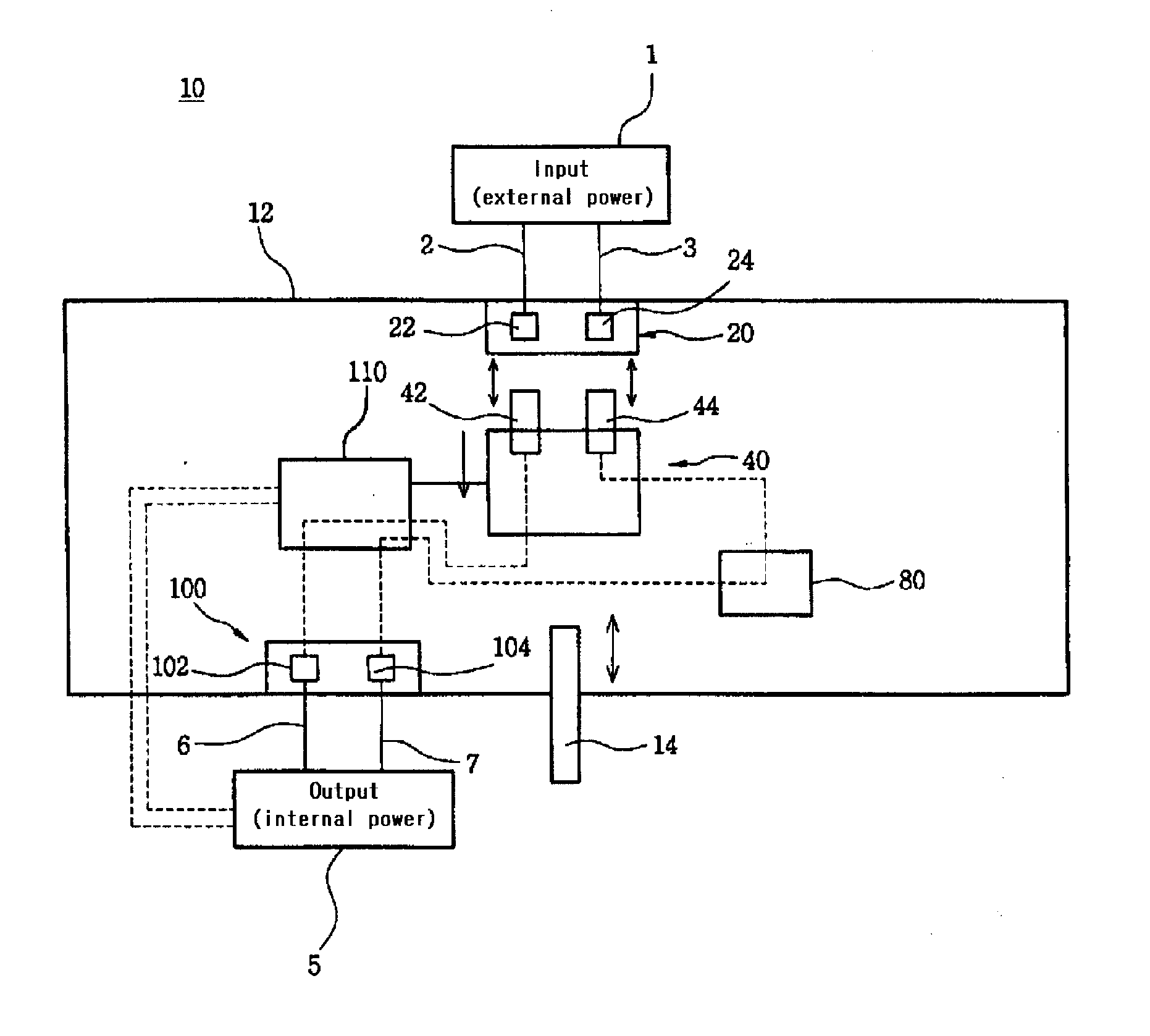
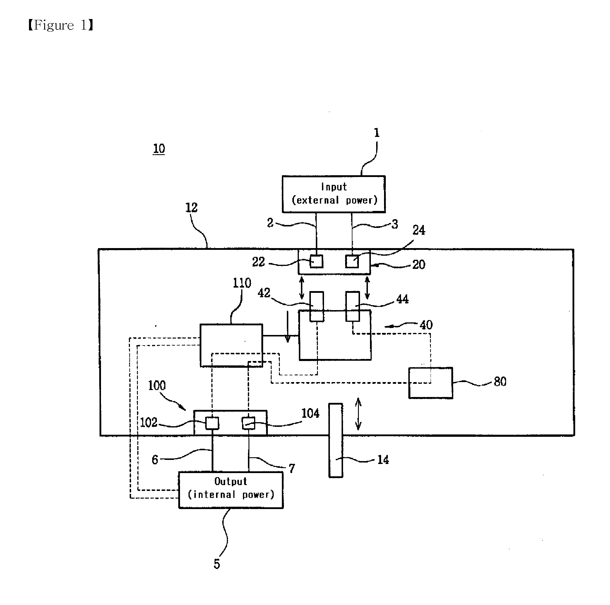
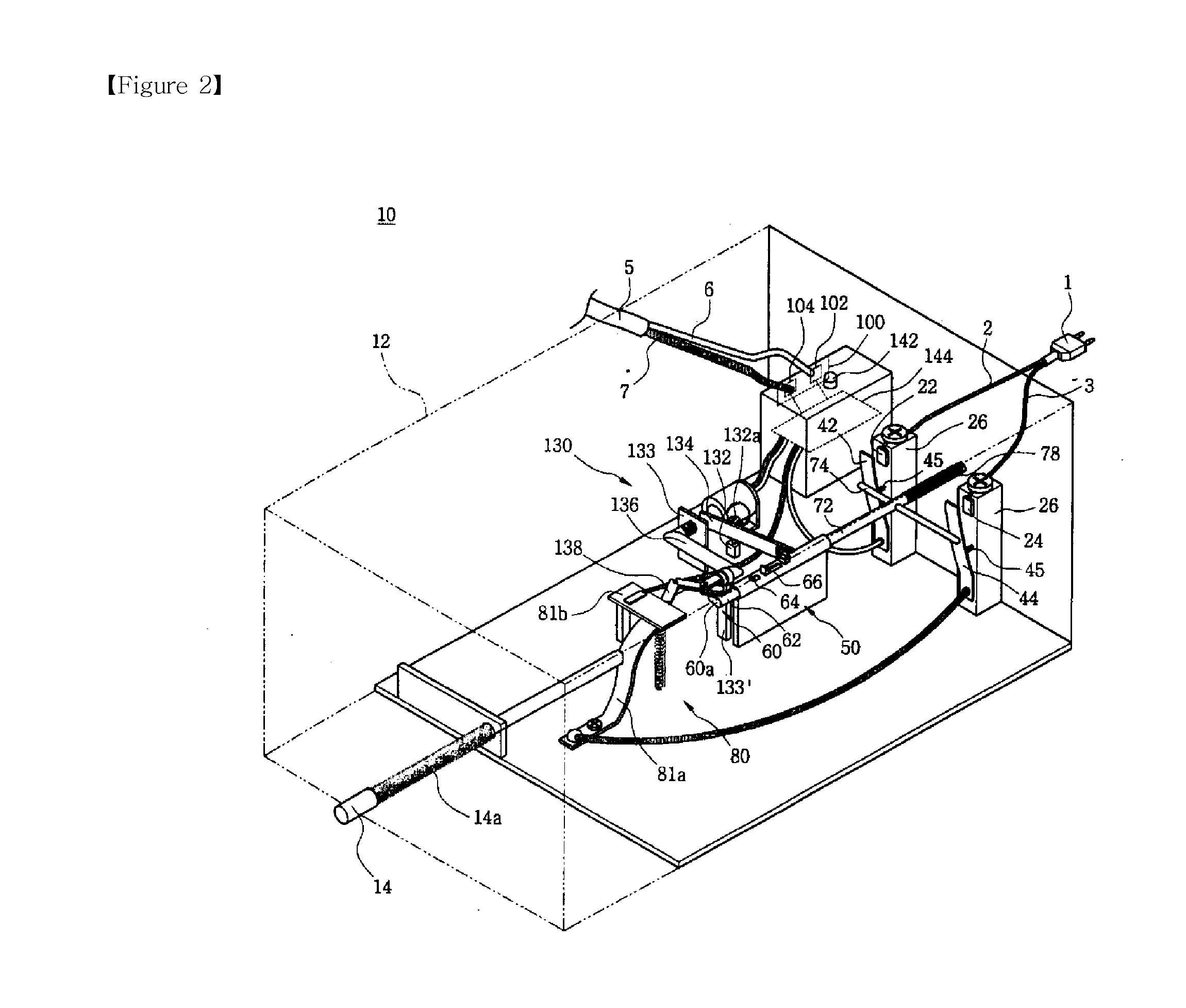
[0115]To accomplish the above object, according to the present invention, there is provided a standby power cut-off switch adapted to be installed in an electric product for completely interrupting supply of an external power to the electric product through a power plug 1, the standby power cut-off switch comprising: a housing 12 securely fixed to the electric product; an input terminal block 20 including a second input terminal 24 which is connected to a second electric wire 3 of the plug 1 in the housing 12 and a first input terminal 22 which is connected to a first electric wire 2 of the plug 1 in the housing 12; an opening / closing unit 40 disposed in the housing 12, the opening / closing unit including a second opening / closing terminal 44 adapted to be brought into close contact with the second input terminal 24 and a first opening / closing terminal 42 adapted to brought into close contact with the first input terminal 22, so that the second opening / closing terminal 44 and the firs...


PUM


Abstract

The present invention provides a standby power cut-off switch which is directly installed in electric products such as TV sets, audio systems, computers, etc., so that even when a power plug is connected to an electrical outlet, supply of an external power to the electric products through the plug is completely interrupted (i.e., double pole interruption) mechanically by means of an automatically controlled OFF signal so as to prevent the consumption of standby power, and in which a first input terminal and a first output terminal are first electrically connected to each other and then a second input terminal and a second output terminal are electrically connected to each other so that a double-pole switch eventually functions as a single-pole switch so as to allow an electrical contact between terminals to be made sequentially, thereby preventing a spark and an electrical shock to the electric product that may occur when the two poles of the switch concurrently come into close contact with a main body of the electric product during the powering on of the electric products.

Description

TECHNICAL FIELD[0001]The present invention relates to a standby power cut-off switch, and more particularly, to such a standby power cut-off switch which is directly installed in electric products such as TV sets, audio systems, computers, etc., so that even when a power plug is connected to an electrical outlet, supply of an external power to the electric products through the plug is completely interrupted (i.e., double pole interruption) mechanically by means of an automatically controlled OFF signal so as to prevent the consumption of standby power, and in which a first input terminal and a first output terminal are first electrically connected to each other and then a second input terminal and a second output terminal are electrically connected to each other so that a double-pole switch eventually functions as a single-pole switch so as to allow an electrical contact between terminals to be made sequentially, thereby preventing a spark and an electrical shock to the electric pro...

Claims


Application Information

Patent Timeline
Patent Type & Authority Applications(United States)
IPC IPC(8): H01H3/02
CPCH01H3/503H01H7/00H02J9/005H01H13/68H01H2300/022H01H13/56Y04S20/20Y02B70/30H01R13/66H02M1/12
Inventor KIM, BYONG HO
Owner KIM BYONG HO
Learn More