
Rotary seal with truncated wave form

Active Publication Date: 2010-10-21
KALSI ENG
View PDF29 Cites 12 Cited by
  • Summary
  • Abstract
  • Description
  • Claims
  • Application Information

AI Technical Summary

Benefits of technology

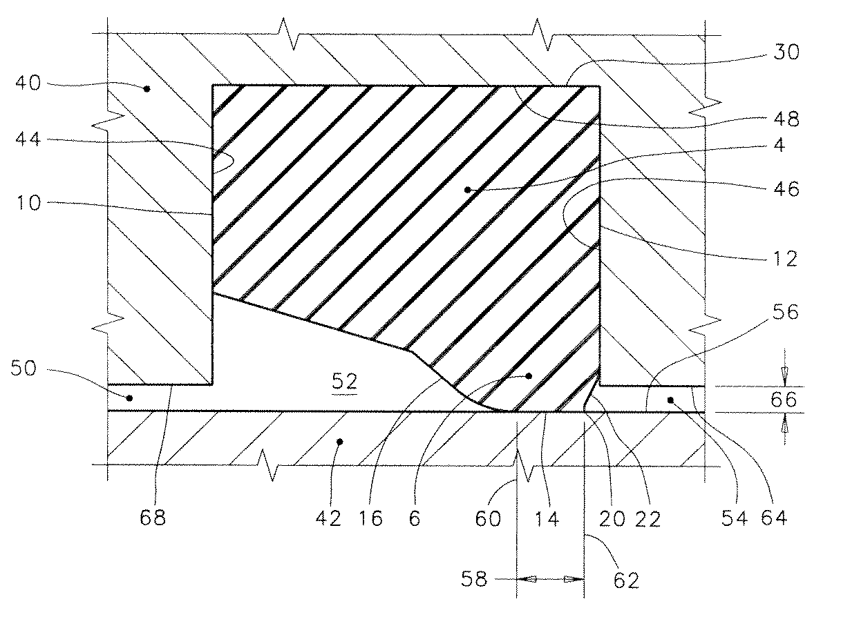
[0057]One objective of the preferred embodiment of the present invention is to provide a hydrodynamic rotary seal having low torque for reduced wear and heat generation. Another objective is improved distribution of lubricant across the dynamic sealing interface, and correspondingly reduced seal wear, particularly in seals that are exposed to skew-resisting axial confinement and / or high differential pressure acting from the lubricant side of the seal. Another objective is to better accommodate high temperature operation in conditions of skew-resisting axial confinement by minimizing local seal volume and by providing geometry that is more immune to thermal expansion-related problems.

Problems solved by technology

Such seals are being challenged to operate at ever-greater temperatures and differential pressures.
Although a good level of lubrication is achieved in many cases, in some cases certain designs fall short when exposed to severe operating conditions.
Due to the high hydrodynamic leakage of such geometry, and the small reservoir size of downhole tools, such seals cannot be used in downhole oil well applications.
For example, media resistance problems, gas permeation, swelling, compression set, and pressure related extrusion damage all become worse at elevated temperature.
This solution is less than perfect in a seal that is axially constrained in accordance with the teachings of U.S. Pat. No. 6,315,302, “Skew Resisting Hydrodynamic Seal,” because the increased seal volume is difficult to accommodate from geometric and interfacial contact pressure standpoints due to the need to accommodate differential thermal expansion between the seal and the hardware it is mounted in.
Secondly, the exclusion edge issue disclosed in U.S. Pat. App. Pub. No. 2007 / 0205563, “Stabilizing Geometry for Hydrodynamic Rotary Seals,” is exacerbated by certain aspects of the U.S. Pat. App. Pub. No. 2009 / 0001671 solution.
This precludes independent manipulation of the size of Dimension A2 and the contact pressure at Location P2, and means that the size of Dimension A2 is undesirably large, especially in high temperature operation and / or operation with skew-resisting confinement.
It is a significant undesirable characteristic of the prior art bi-directional rotation seals that lubrication of the un-swept zone is impaired in severe operating conditions.
As the aforementioned sizes increase and the size of the swept zone decreases, lubrication is impaired, causing the seal to generate more and more heat due to increasing asperity friction, and causing a loss of lubricant film viscosity.
These factors further increase seal temperature, compounding the problem and leading to an unsustainable runaway operating condition.

Method used


Image

  • Rotary seal with truncated wave form
  • Rotary seal with truncated wave form
  • Rotary seal with truncated wave form

Examples


Embodiment Construction

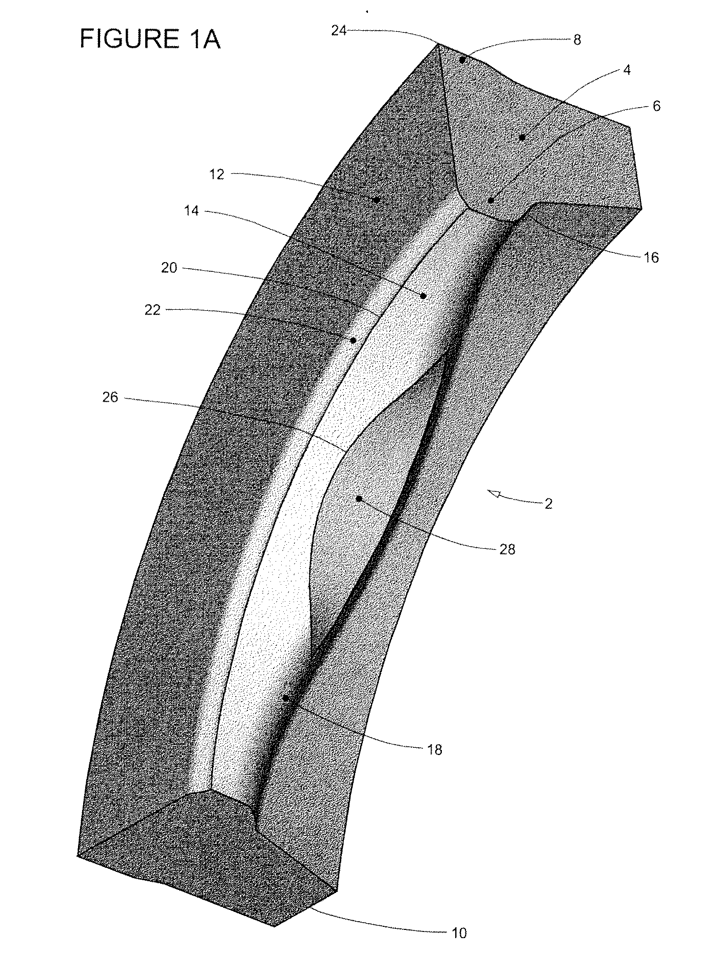
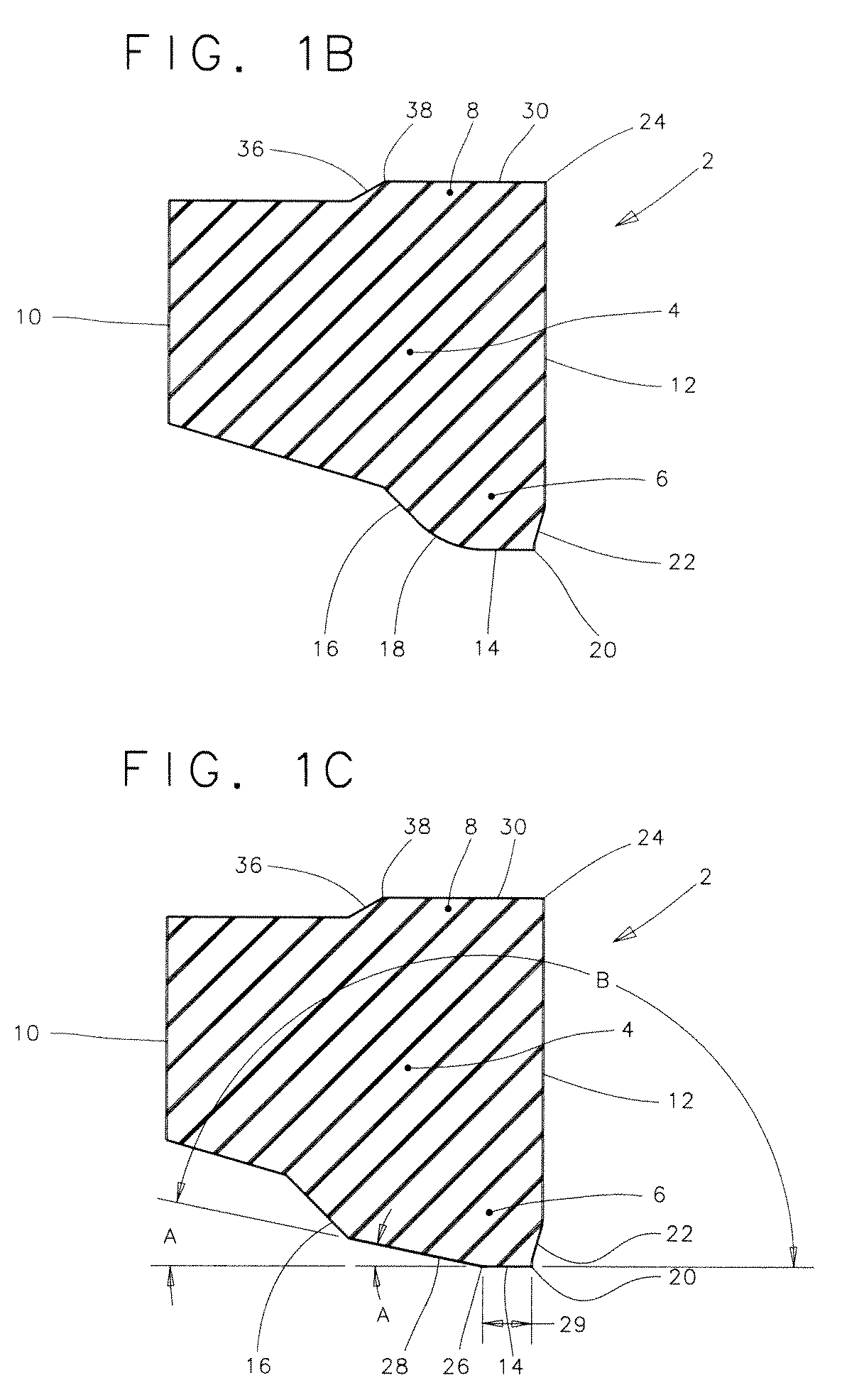
[0068]Features throughout this specification that are represented by like numbers have the same basic function. The ring-like rotary seal according to the preferred embodiments of the present invention is generally referred to as reference number 2 in the drawings.

[0069]FIGS. 1A-1E

[0070]FIGS. 1A to 1E represent a preferred embodiment of the present invention. These figures should be studied together to best understand the preferred embodiment.

[0071]FIG. 1A

[0072]FIG. 1A is a fragmentary shaded perspective view representing a ring-shaped rotary seal shown generally at 2 that represents a preferred embodiment of the present invention. The rotary seal 2 is shown in its uncompressed, uninstalled condition.

[0073]The rotary seal 2 has a ring-like seal body 4 of generally circular configuration. The term “ring-like” is used with the understanding that the term “ring” is commonly understood to encompass shapes other than those that are perfectly circular. As an example, a decorative finger r...


PUM


Abstract

The present invention is a generally circular rotary seal that establishes sealing between relatively rotatable machine components for lubricant retention and environmental exclusion, and incorporates seal geometry that interacts with the lubricant during relative rotation to distribute a lubricant film within the dynamic sealing interface. A preferably curved elevated contact pressure zone serves to maximize interfacial lubrication in critical areas during severe operating conditions by utilizing lubricant that would otherwise escape at the trailing edge of the hydrodynamic waves. The zones are produced by geometry that serves to minimize lubricant shear area, seal torque, seal volume, and wear, while ensuring retrofitability into the seal grooves of existing equipment.

Description

CROSS-REFERENCE TO RELATED APPLICATIONS[0001]This application claims the benefit of U.S. Provisional Application Ser. No. 61 / 212,179 filed Apr. 8, 2009, entitled “Rotary seal with improved environmental exclusion.” Applicant incorporates by reference herein U.S. Provisional Application Ser. No. 61 / 212,179 in its entirety.BACKGROUND OF THE INVENTION[0002]1. Field of the Invention[0003]This invention relates to hydrodynamic rotary seals for bi-directional or uni-directional rotation that are used to retain a lubricant and exclude an environment. More specifically, this invention relates to a feature that improves seal lubrication in adverse conditions such as high operating temperature, skew-resisting confinement, high differential pressure, high initial compression, adverse tolerance accumulation, circumferential compression, high modulus seal materials, dynamic runout, reversing differential pressure, thin viscosity lubricants, third body seal surface wear, and / or material swell (co...

Claims


Application Information

Patent Timeline
IPC IPC(8): F16J15/32
CPCF16J15/3244F16J15/164
Inventor SCHROEDER, JOHN ERICKDIETLE, LANNIE LAROY
Owner KALSI ENG
Learn More