Structural i-beam automotive suspension arm

a technology of i-beam and automotive suspension, which is applied in the direction of i-beam suspension arms, resilient suspensions, vehicle components, etc., can solve the problems of reduced strength and stiffness, use of a number of complex manufacturing processes, and non-uniform shape, so as to achieve superior i-beam section and facilitate manufacturing.

Active Publication Date: 2010-10-21
MULTIMATIC INC
View PDF5 Cites 14 Cited by
  • Summary
  • Abstract
  • Description
  • Claims
  • Application Information

AI Technical Summary

Benefits of technology

[0011]Accordingly, it would be advantageous to create a suspension control arm that could provide high inherent stiffness and strength while maintaining relatively low mass using a low cost manufacturing technique such as sheet metal press-forming. It has been proven that for large volume applications such as those dictated by the automotive industry, sheet metal press-forming is the most cost-effective method of manufacturing structural components. Almost every vehicle currently produced utilizes a body structure and selected subframes constructed almost entirely from either aluminum or steel stampings manufactured using press-forming techniques. The aim of the present invention, therefore, is to utilize metal press-forming in the manufacture of a vehicle suspension control arm.
[0021]In a preferred embodiment of the present invention the required plan view shape, namely an “A”, “L”, or other appropriate shape for the application, is created by rigidly attaching a bushing support structure to a main arm component using MIG, TIG, ARC or Laser welding or similar means. The main arm component is constructed in an identical manner to the sheet metal stamped component previously described but is of a simpler plan view shape that is easier to manufacture than a fully bifurcated configuration. The bushing support structure is configured as simple metal stamping of either open or closed section and is adapted to accept a round bushing support. In this manner the highly complex plan view shapes that are often dictated by the vehicle's suspension geometry requirements can be accommodated with a sheet metal stamped component of relatively simple plan view shape while maintaining all the advantages of the superior I-beam section previously described.

Problems solved by technology

Reducing weight normally results in a reduction of both strength and stiffness.
The requirement for optimized control arm structures to be non-uniform in shape has driven the use of a number of complex manufacturing processes.
Because of the complex shapes involved it is very difficult to manufacture an optimized vehicle control arm from simple press formed metal stampings.
This type of structural section is far less efficient in resisting in-plane bending loads than an I-beam and requires a significant overlap of material to facilitate the required weld fillet joint.
This material overlap is ultimately structurally redundant and results in a heavier solution than alternative cast or forged configurations.
However, Kusama does not teach a method for creating a true I-beam section using press-forming techniques.
Although I-beam sections have been created by combining two relatively simple stampings in this way, the flanges have been half the thickness of the web, which has resulted in poor structural performance. FIG. 4 illustrates a cross-sectional view of a typical prior art I-beam suspension control arm constructed from two cup-shaped press-formed stampings.
This is not an optimal structural configuration.
However the I-beam section of Howell possesses the same limitation as Layman in that the flanges and the web are of equal material thickness.

Method used


Image

  • Structural i-beam automotive suspension arm
  • Structural i-beam automotive suspension arm
  • Structural i-beam automotive suspension arm

Examples


Embodiment Construction

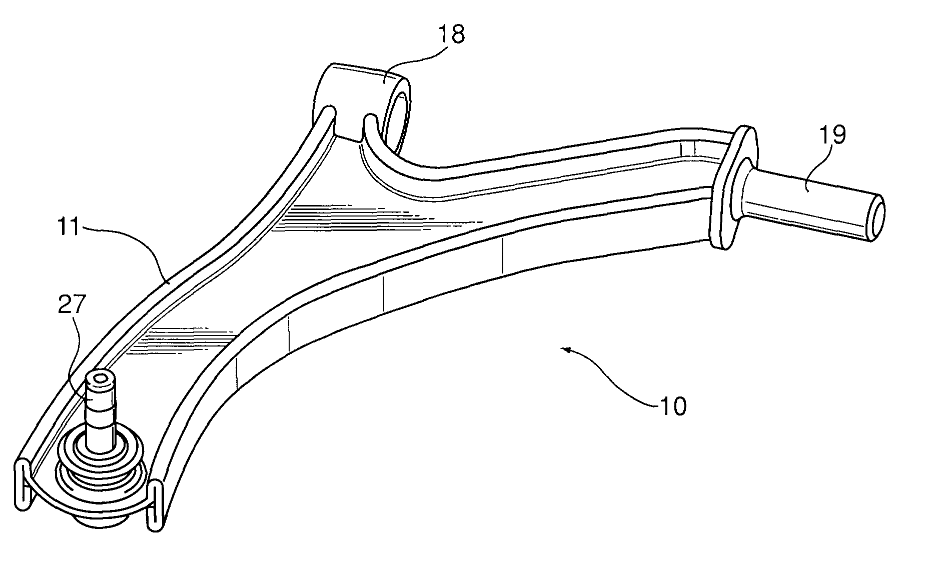
[0036]Referring to FIGS. 5, 6, 7 and 8, a vehicular suspension control arm (10) is substantially constructed from a complex single piece, sheet metal stamped component (11), a round bushing support (18), an in-line pin bushing support (19) and a ball joint (27). The sheet metal stamped component (11) is manufactured by press-forming a uniform thickness, flat sheet of steel, aluminum or other suitable metal (e.g. titanium, tungsten, etc.) or alloy into a required plan view shape which is dictated by the vehicle's suspension geometry requirements. Additionally, the stamped component is configured, during the press-forming process, with a single material thickness web portion (12) and two flange portions (13) at opposite sides of the central web portion (12). Each flange portion (13) includes an upstanding closed section (14) and downstanding closed section (15) formed with a continuous returned segment (16) that is double returned onto one of the closed sections so that the trim end (...


PUM

PropertyMeasurementUnit
thicknessaaaaaaaaaa
distanceaaaaaaaaaa
stiffnessaaaaaaaaaa

Abstract

A structural element comprising a vehicle suspension control arm is constructed from a complex, single piece, sheet metal stamped component formed from a material of uniform thickness. The stamping is configured with the correct plan view shape and formed into an I-beam cross-section comprising a central web portion and two flange portions. The central web portion is configured as a single material thickness and the flange portions comprise upstanding and downstanding closed sections with a continuous double returned segment. The open ends of the sheet metal terminate at or near the central web portion and are welded to the web portion, and in an alternative embodiment also to the continuous double returned segment, to create a favorable structural I-beam section with flange portions twice the thickness of the web portion.

Description

FIELD OF THE INVENTION[0001]This invention applies to a manufacturing process for structural elements formed from sheet metal, more particularly to those components requiring high stiffness to weight and strength to weight ratios. In particular, the invention applies to an automotive suspension arm.DESCRIPTION OF THE PRIOR ART[0002]Most modern road vehicles utilize some form of suspension system to isolate the passenger compartment from wheel disturbances caused by irregularities in the road surface. These suspension systems normally include some form of energy storage medium such as a spring, a device to control the spring's motion such as a damper, and a linkage arrangement to control the kinematics of the wheel movement. This combination of components is configured to allow the vehicle's wheels to move up and over road irregularities in a controlled manner. The most common form of linkage arrangement is a four-bar linkage configuration, constructed from the spindle assembly, the ...

Claims


Application Information

Patent Timeline
Patent Type & Authority Applications(United States)
IPC IPC(8): B60G7/00B60G3/00
CPCB23P2700/14B23P15/00B60G7/001B60G2200/144B60G2206/81022B60G2206/8201B60G2206/124B60G2206/8103B60G2206/017B60G2206/014B60G2204/416B60G2200/154B60G2206/722B60G2206/16B60G2206/14B60G2206/122B60G3/20
Inventor GUTTILLA, MICHAELBROUGHTON, CHRISSPARROW, THOMAS ALEXANDER
Owner MULTIMATIC INC
Why Eureka
Try Eureka