Weldless vehicular suspension control arm

a control arm and vehicle technology, applied in the field of automotive components, can solve the problems of reduced strength and stiffness, use of a number of complex manufacturing processes, and non-uniform shape, and achieve the effects of low mass, high inherent stiffness and strength, and low cos

Active Publication Date: 2022-05-12
MULTIMATIC INC
View PDF39 Cites 1 Cited by
  • Summary
  • Abstract
  • Description
  • Claims
  • Application Information

AI Technical Summary

Benefits of technology

[0016]Accordingly, it would be advantageous to create a suspension control arm that could provide high inherent stiffness and strength while maintaining relatively low mass using a low cost manufacturing technique such as sheet metal press-forming. It has been proven that for large volume applications such as those dictated by the automotive industry, sheet metal press-forming is the most cost-effective method of manufacturing structural components. Most vehicles currently produced employ a body structure and selected subframes constructed almost entirely from either aluminum or steel stampings manufactured using press-forming techniques. An aim of the present invention, therefore, is to utilize metal press-forming in the manufacture of a vehicle suspension control arm.
[0017]It would also be advantageous to produce a control arm using relatively light weight, pre-coated, sheet metal steel without the use of welding. In addition, reduced capital costs for equipment and floor space, reduced costs of materials and energy, reduced inspection costs, reduced part fatigue and improved vehicle performance and fuel efficiency owing to lighter weight parts, would all be beneficial.

Problems solved by technology

Reducing weight normally results in a reduction of both strength and stiffness.
The requirement for optimized control arm structures to be non-uniform in shape has driven the use of a number of complex manufacturing processes.
Owing to the complex shapes involved, it is difficult to manufacture an optimized vehicle control arm from simple press formed metal stampings.
Although precise shapes can be formed, the control arm tends to be solid with significant attendant weight.
Cast control arms are strong but tend to be somewhat brittle.
The casting process is more expensive than other manufacturing processes.
Although aluminum is lighter than steel and corrosion resistant, it is considerably more expensive.
Although a forged part tends to have greater tensile strength than a cast part, the process is also expensive since significant heat is required and there tends to be a significant amount of scrap.
Aluminum lends itself to forging, but the significant scrap adds to the cost, even though it is fairly easily recycled.
This material overlap is ultimately structurally redundant and may result in a heavier solution than alternative cast or forged configurations.
If a butt jointed construction is used, without material overlap, the strength and integrity of the welding to create the joint is even more critical and the part is more difficult to manufacture.
Although a single piece control arm may be produced from sheet metal steel in an essentially U-shaped structure, a relatively heavy gage steel is required to handle the significant loads to which the control arm is subject.
A heavier part is generally undesirable and the additional cost of material may be prohibitive.
Moreover, the U-shaped structure renders it difficult to locate a high concentration of material around the edges of the “A” or “L” formation to maximize the in-plane second moment of area values.
A disadvantage of most prior art control arms produced using the above described techniques is that an aperture for the ball joint at the knuckle end must be welded to the control arm, as illustrated in FIG. 4, or the aperture must be stamped into the press-formed part thus creating an additional step, disruption of the sheet metal and additional scrap.
This creates additional welding steps, with the opportunity for misalignment of the bushing seats or welding flaws.
The process of welding tends to disrupt the anti-corrosion coatings on the sheet metal thus exposing the part to corrosion at the weld.
Although some parts may be electroplated with a protective coating post-welding, this is often difficult with larger, irregularly shaped parts.
Post-welding electroplating of a part is expensive and requires extra processing time and floor space.
In addition, welding may result in a joint with uneven strength at various points along the weld.
Since control arms are typically subjected to continual stresses while a vehicle is in motion, welding irregularities may result in stress failure at the welds.
Welded joints are generally subject to poorer fatigue performance than a jointless metal part.
Moreover, the welding process produces a heat-affected zone along both sides of the weld that typically exhibits lower strength than the remainder of the sheet metal which thus reduces the overall strength of the part.
Modern welding techniques involve robots, weld cells, welding wire and attendant infrastructure, including post-welding inspection, all of which contribute to the cost of manufacture.
Welding also adversely affects the air quality in the welding area and consumes significant electricity.

Method used


Image

  • Weldless vehicular suspension control arm
  • Weldless vehicular suspension control arm
  • Weldless vehicular suspension control arm

Examples


Embodiment Construction

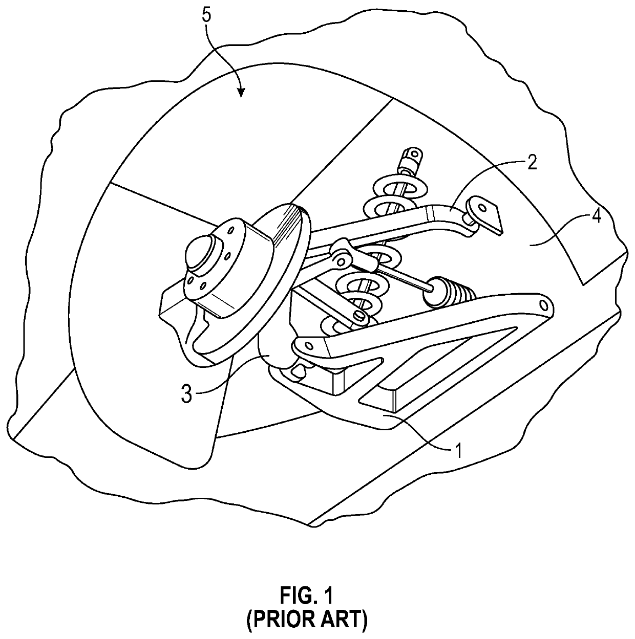
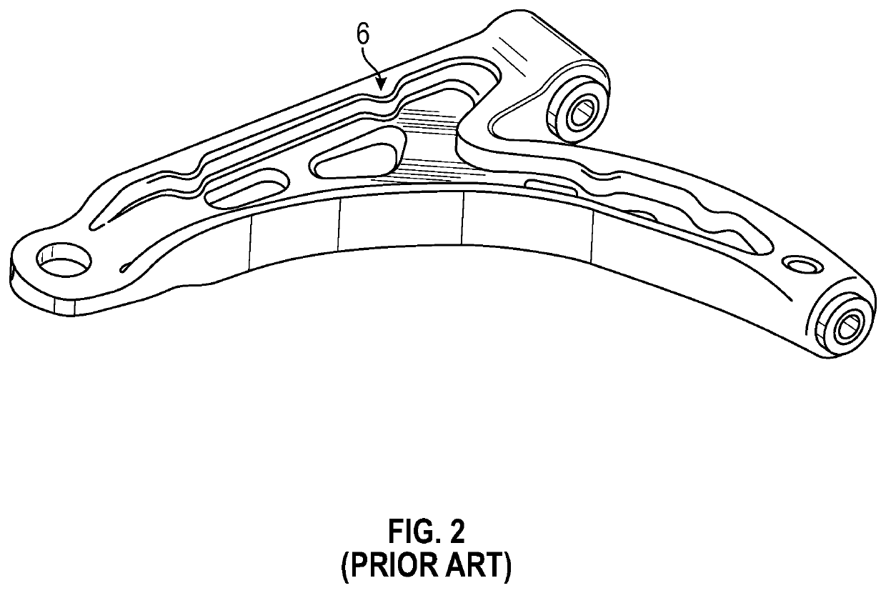
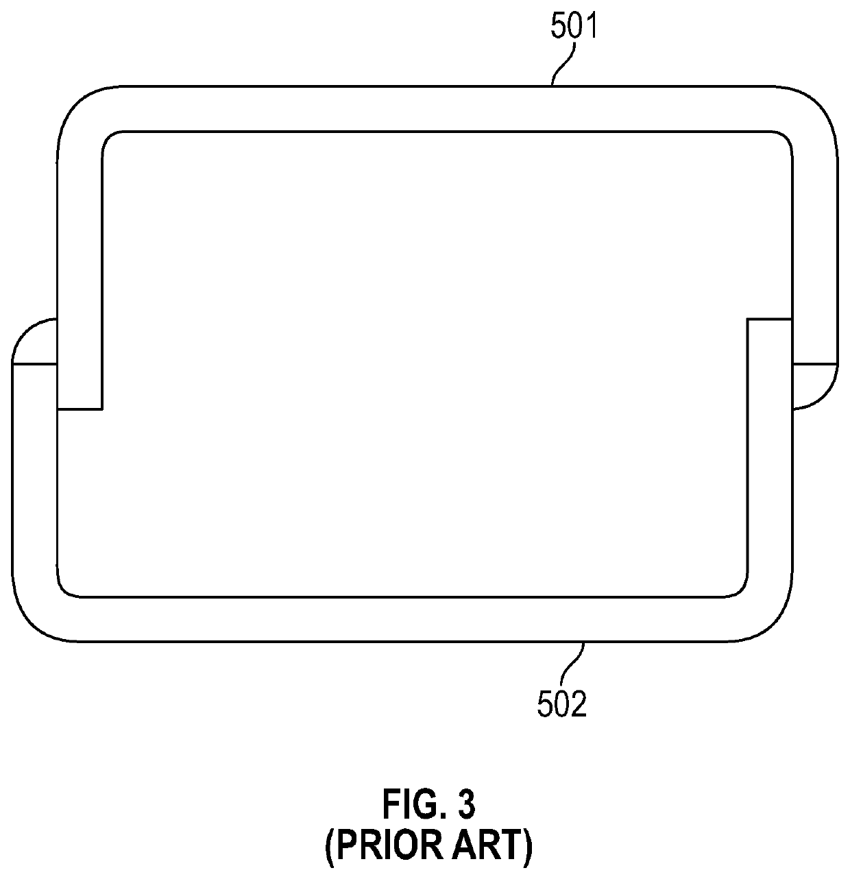
[0053]FIGS. 5 to 9 illustrate a preferred embodiment of the weldless vehicle suspension control arm 15 of the invention. A first arm component 12 and a second arm component 14 are stamped from sheet metal. The preferred material is a steel sheet pre-coated for corrosion protection. Given the nature of this construction, a lighter gage sheet metal may generally be used than with a corresponding prior art welded construction, such as illustrated in FIG. 3 and FIG. 4.

[0054]First arm component 12 and second arm component 14 have certain common features. Each comprises an outer wall 16 and two side walls 18. Each arm component has an integral bushing seat receiving aperture 20 adjacent a first end 22 of the arm component. With appropriate stamping, the apertures 20 are formed from the same material comprising the rest of the arm component without the need to weld or otherwise attach a separate component with a bushing seat to the control arm, as typical in prior art manufacture. In addit...


PUM


Abstract

A vehicular suspension control arm comprises a first arm component and a second arm component formed from sheet metal, each arm component comprising an outer wall and two side walls, bushing connecting means adjacent a first end, at least one bracket receiving rivet aperture adjacent a second end, at least one component connecting rivet aperture located between the first end and the second end, a ride bushing and a handling bushing, a ball joint bracket comprising bracket rivet apertures corresponding to the at least one bracket receiving rivet aperture adjacent the second end of each of the first and second arm components and a plurality of rivets. When constructed, the ball joint bracket is riveted to both the first and second arm components adjacent the second end thereof via the at least one bracket receiving rivet aperture and the corresponding at least one bracket rivet aperture, the first arm component is riveted to the second arm component at the at least one component connecting rivet aperture, the ride bushing is connected at the first end of the first arm component and the handling bushing is connected at the first end of the second arm component.

Description

CROSS-REFERENCE TO RELATED APPLICATIONS[0001]This application claims priority to U.S. Provisional Application No. 62 / 896,303 which was filed on Sep. 5, 2019, and U.S. Provisional Application No. 62 / 979,532 which was filed on Feb. 21, 2020, and are incorporated herein by reference.FIELD OF THE INVENTION[0002]This invention relates to the field of automotive components, in particular an automotive suspension control arm.BACKGROUND OF THE INVENTION[0003]Most modern road vehicles use some form of suspension system to isolate the passenger compartment from wheel disturbances caused by irregularities in the road surface. These suspension systems normally include some form of energy storage medium such as a spring, a device to control the spring's motion such as a damper, and a linkage arrangement to control the kinematics of the wheel movement. This combination of components is configured to allow the vehicle's wheels to move up and over road irregularities in a controlled manner. The mos...

Claims


Application Information

Patent Timeline
Patent Type & Authority Applications(United States)
IPC IPC(8): B60G7/00
CPCB60G7/001B60G2204/41B60G2206/8206B60G2206/017B60G2206/122B60G2204/416B60G2206/124B60G2206/16B60G2206/722F16B5/04
Inventor PIVA, BRIAN WILLIAM
Owner MULTIMATIC INC
Why Eureka
Try Eureka