

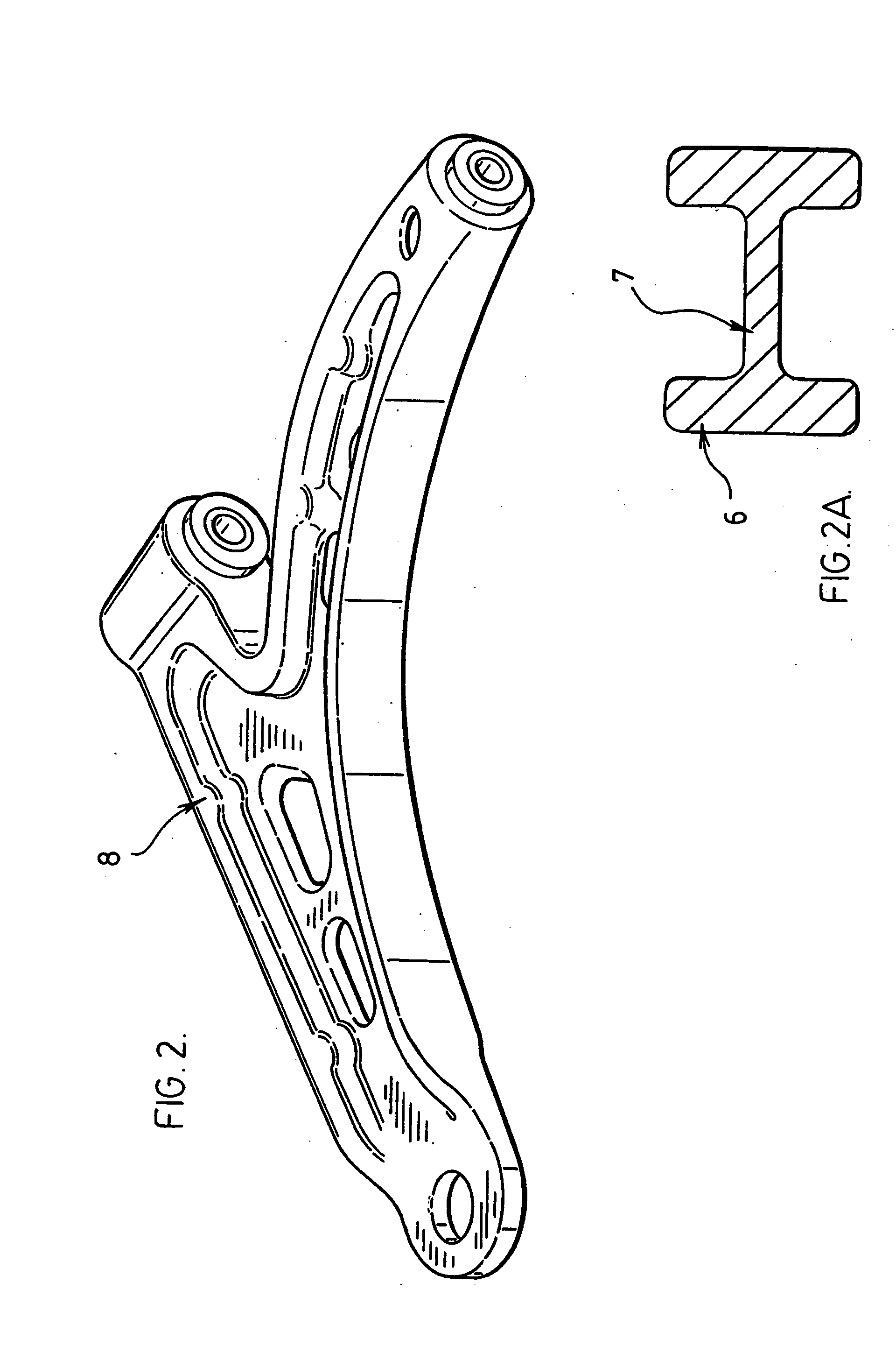
Structural i-beam automotive suspension arm
a technology of i-beam and automotive suspension, which is applied in the direction of resilient suspensions, vehicle components, metal-working apparatus, etc., can solve the problems of reduced strength and stiffness, use of a number of complex manufacturing processes, and non-uniform shape, so as to achieve high inherent stiffness and strength, low mass, and low cost
- Summary
- Abstract
- Description
- Claims
- Application Information
AI Technical Summary
Benefits of technology
Problems solved by technology
Method used
Image

Examples
Embodiment Construction
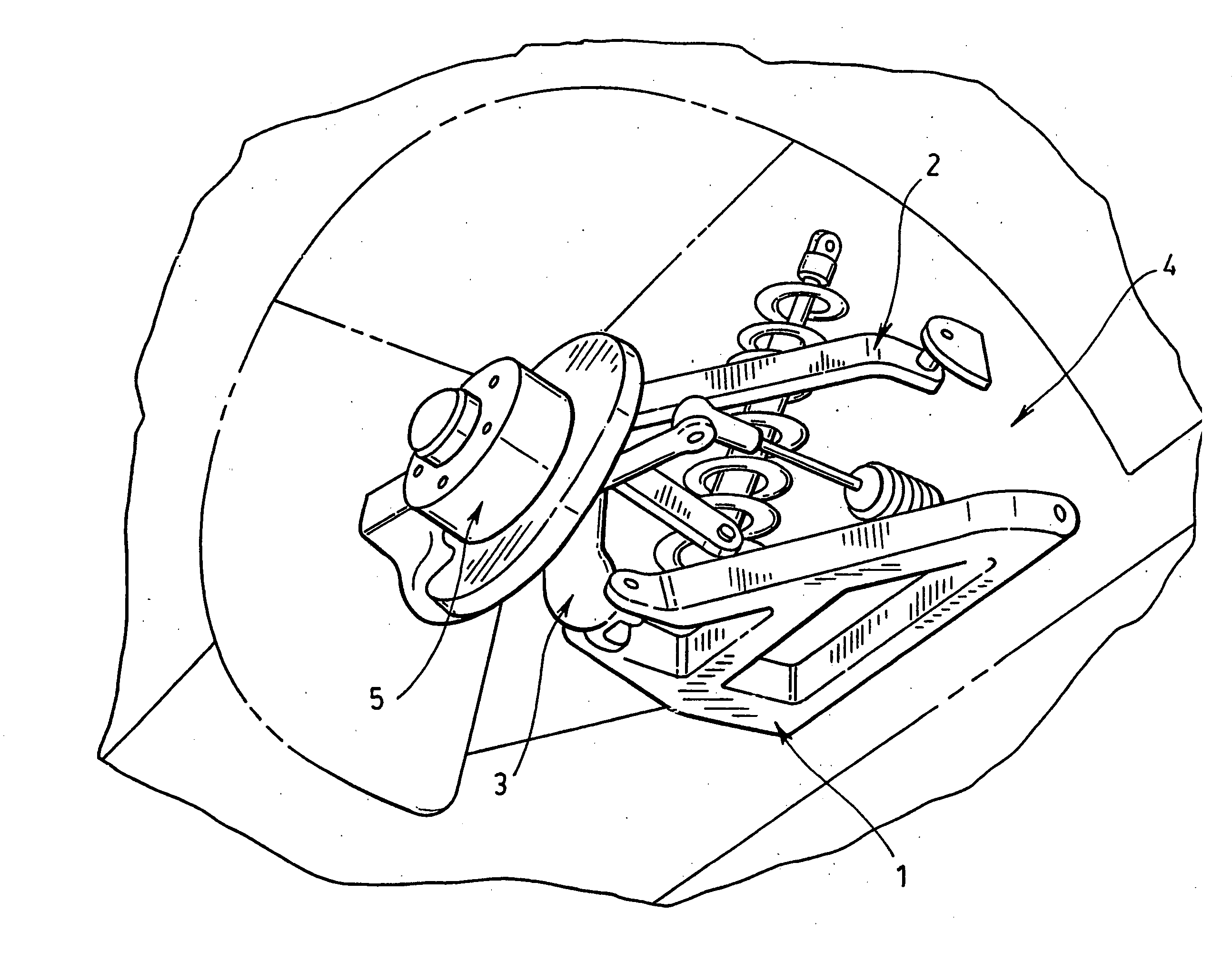
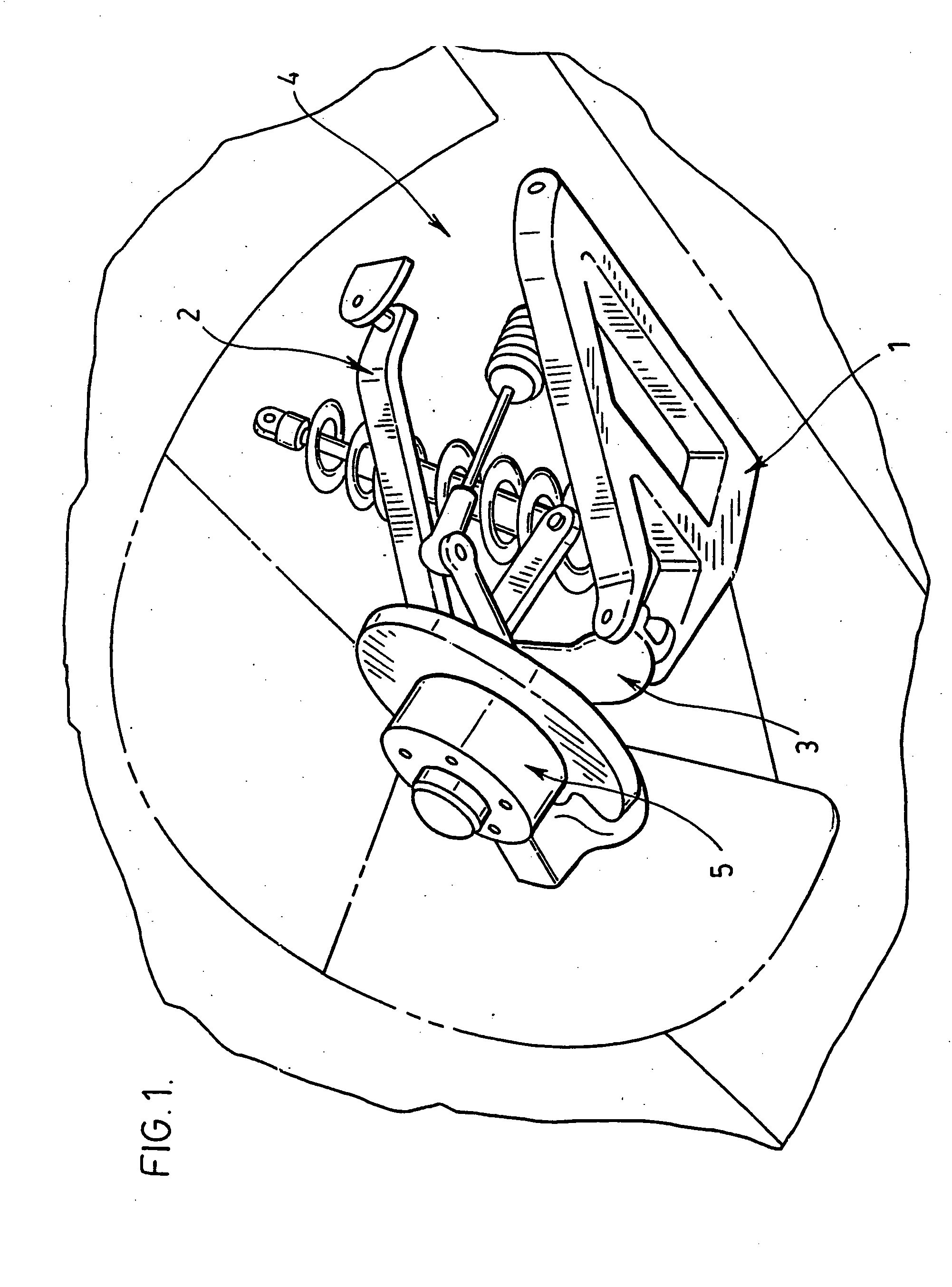
[0029] Referring to FIGS. 5, 6, 7, 7A and 8, a vehicular suspension control arm (10) is substantially constructed from an upper stamped component (11) and a lower stamped component (12). Both the upper and lower stamped components are manufactured by press-forming a flat sheet of steel aluminum or other suitable metal or alloy into a required plan view shape which is dictated by the vehicle's suspension geometry requirements. Additionally, both the upper and lower stamped components are configured, during the press-forming process, with a cup-shaped section containing upstanding flanges (13) in which the material is filly returned back upon itself to effectively double the section thickness in this area. These fully returned flanges (13), of double material thickness run around the entire periphery of the stamped components with the exception of localized areas requiring special formations to facilitate the vehicle body attachments (14)(15) and the spindle attachment (20).
[0030] Th...
PUM
| Property | Measurement | Unit |
|---|---|---|
| Thickness | aaaaa | aaaaa |
Abstract
Description
Claims
Application Information