Fuell consumption reduction device

Inactive Publication Date: 2010-10-21
A TO Z INNOVATIONS
View PDF20 Cites 4 Cited by
  • Summary
  • Abstract
  • Description
  • Claims
  • Application Information

AI Technical Summary

Benefits of technology

[0018]wherein the electronic circuit is adapted to reduce noise and stabilize the voltage signal of the vehicle.
[0019]In an exemplary embodiment of the invention, the electronic circuit is adapted to reduce noise and stabilize the voltage signal of the vehicle by absorbing excess voltage from the voltage signal of the vehicle and supplementing deficient voltage of the voltage signal. Optionally, the device further comprises a front panel that provides an indication if the device is functional. In an exemplary embodiment of the invention, the indication is provided by a LED that is a part of the electronic circuit. Optionally, the electronic circuit is adapted to provide an indication if the status of the battery of the vehicle is below a pre-selected value. In an exemplary embodiment of the invention, the pre-selected value is user selectable. Optionally, the device further comprises a switch to turn the device on or off during use of the vehicle.
[0021]preparing an electronic circuit that is adapted to reduce noise and stabilize the voltage signal provided by the battery of a vehicle connected in parallel to the electronic circuit;

Problems solved by technology

Fuel consumption is a key expense in the use of motorized vehicles.
However regardless of the type of fuel used it remains a key expense in the usage of the vehicle.
The ECU is designed to function at a specific voltage, however in the real world during use of the vehicle the electrical currents in the vehicle are situated in many different states and affected by interferences, for example working with the lights off or with the lights on, working with the radio off or on, working with heaters / coolers and fans off or on, poor (e.g. corroded) contacts and strong contacts, and many other situations.
As a result the electrical currents in the vehicle are not a perfect regulated voltage DC signal but rather a noisy signal fluctuating around the specific voltage.
The noisy signal has a detrimental affect on the accuracy of the functionality of the ECU, thus preventing fuel consumption from reaching its optimal state.

Method used


Image

  • Fuell consumption reduction device
  • Fuell consumption reduction device
  • Fuell consumption reduction device

Examples


Embodiment Construction

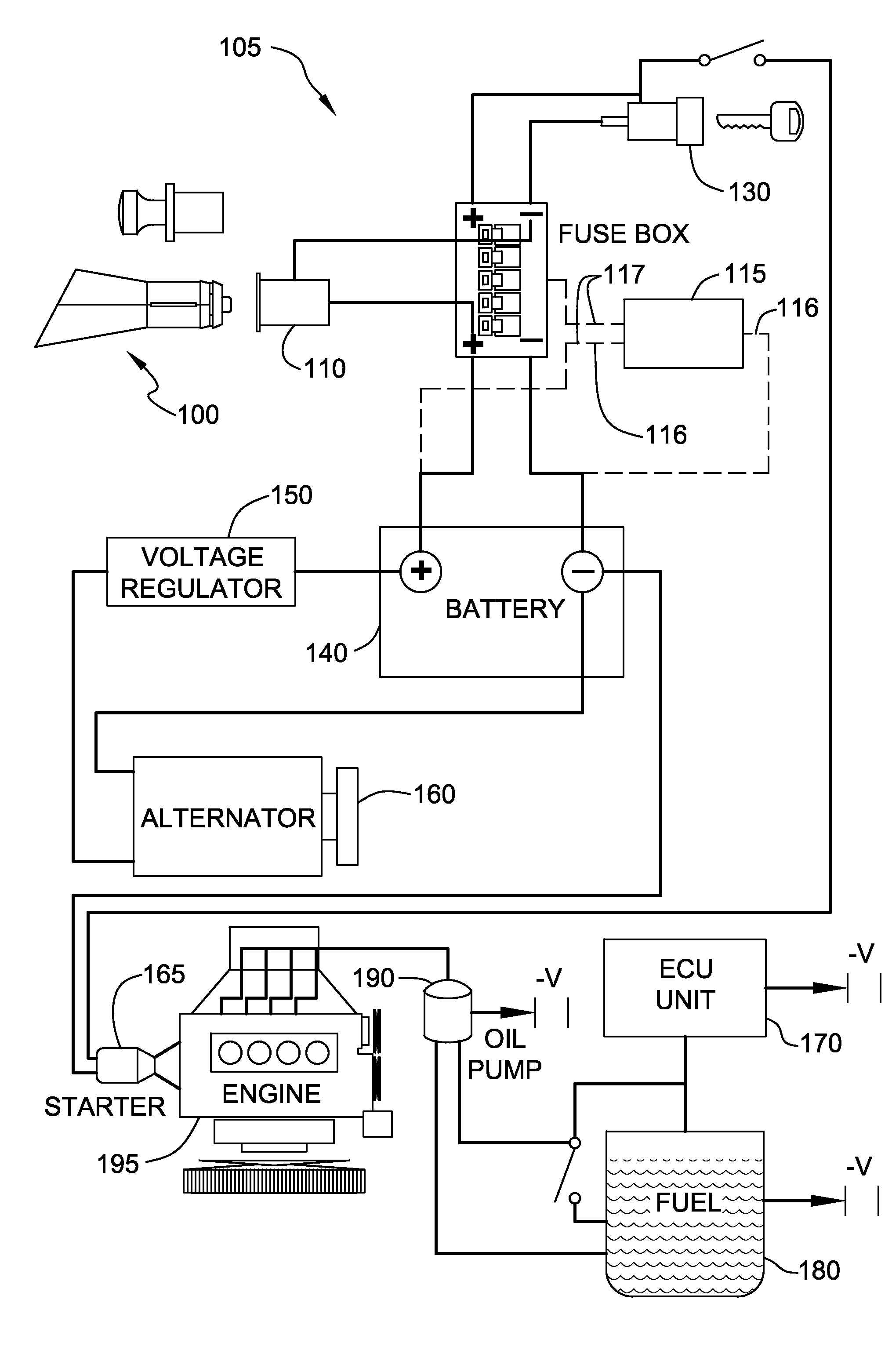
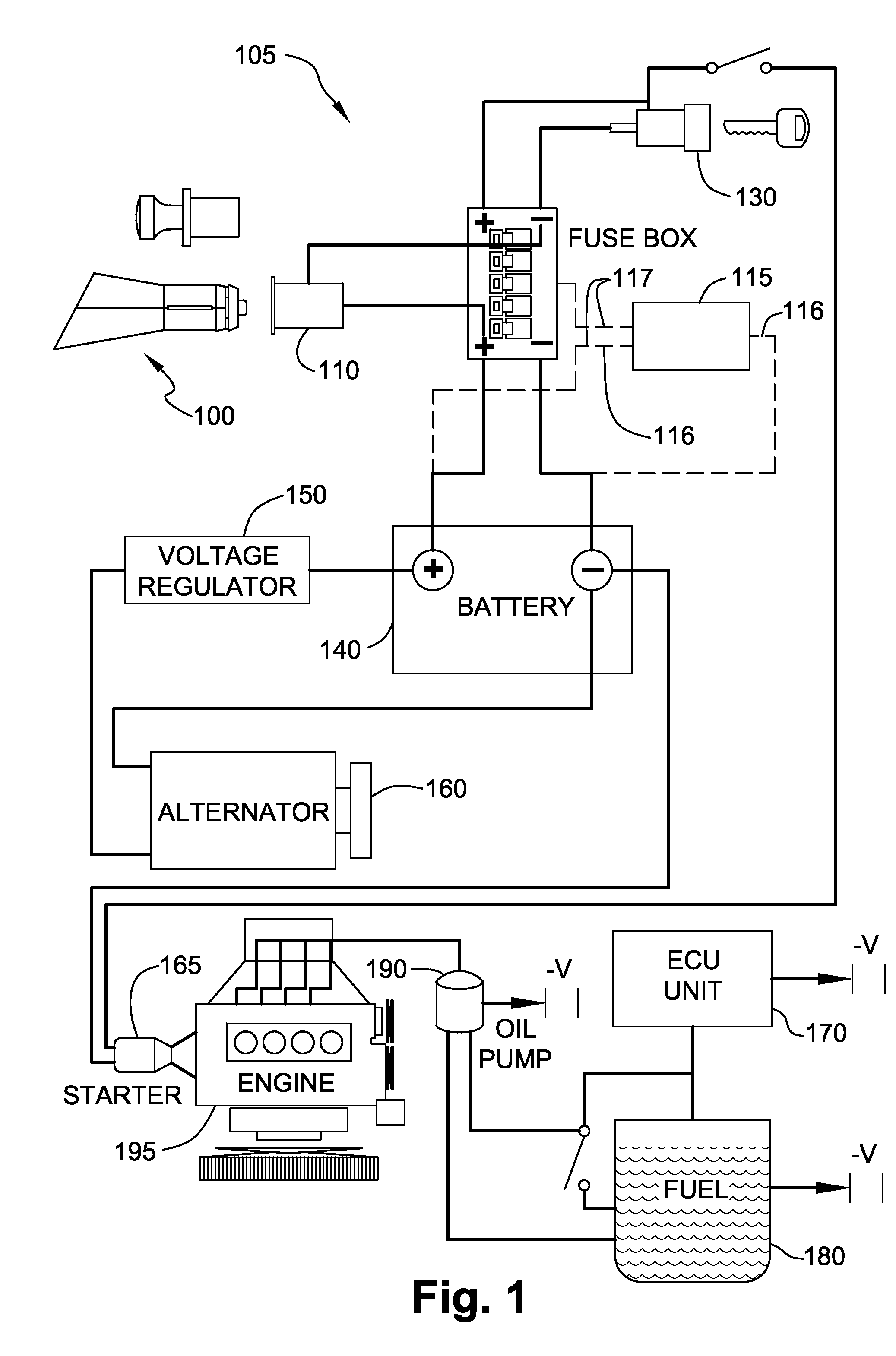
[0033]FIG. 1 is a schematic illustration of an electrical circuit 105 of a vehicle for deploying a fuel consumption reducer 100, according to an exemplary embodiment of the invention. In an exemplary embodiment of the invention, fuel consumption reducer 100 is Inserted into a cigarette lighter socket 110 of the vehicle. The cigarette lighter socket 110 is connected via a fuse box 120 to a battery 140 that serves as the basic power source of the vehicle. During use of the vehicle, the power from battery 140 is supplemented with power from an alternator 160, which provides power through a voltage regulator 150. Alternator 160 additionally charges battery 140.

[0034]A switch 130 provides power to a starter 165 to start engine 195 of the vehicle. Once engine 195 is started an electrical control unit (ECU) 170 controls an oil pump 190 and fuel pump 180, to provide the correct amount of fuel and oil to engine 195 while the vehicle is being used.

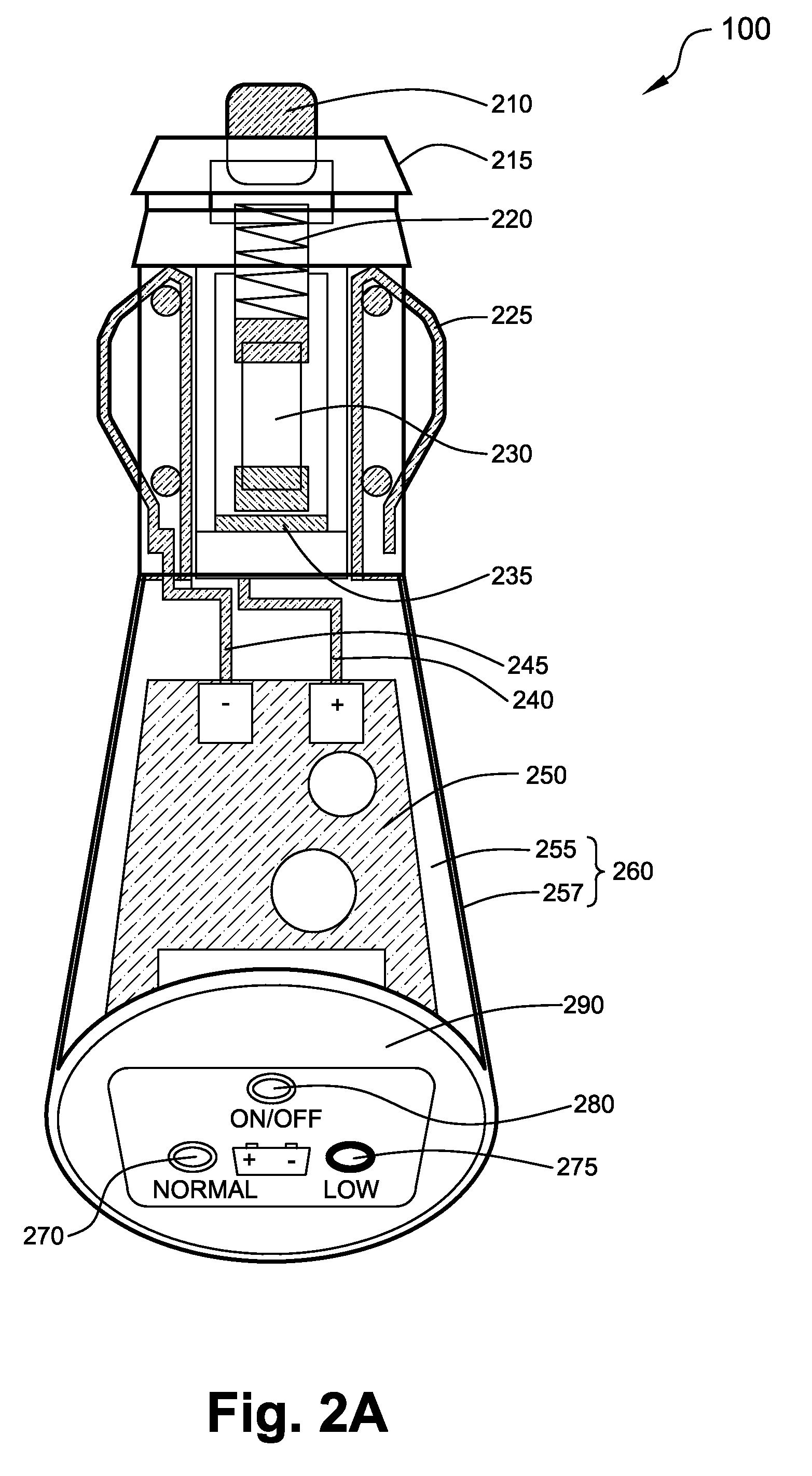
[0035]In an exemplary embodiment of the inven...


PUM


Abstract

A fuel consumption reduction device for deployment in a vehicle, including:an electronic circuit, an encasement adapted to fit into the cigarette lighter socket of the vehicle and to enclose the electronic circuit, a positive terminal positioned on one end of the encasement that is adapted to form contact between the electronic circuit and the positive voltage source connection of the vehicle located in the cigarette lighter socket, at least one negative terminal positioned on the side of the encasement that is adapted to form contact between the electrical circuit and the negative voltage connection of the cigarette lighter; and wherein the electronic circuit is adapted to reduce noise and stabilize the voltage signal of the vehicle.

Description

FIELD OF THE INVENTION[0001]The present Invention relates generally to a device for reducing the consumption of fuel by motorized vehicles and more specifically to reducing fuel consumption through the use of an electrical circuit.BACKGROUND OF THE INVENTION[0002]Fuel consumption is a key expense in the use of motorized vehicles. Motorized vehicles burn fuel of various types, for example gasoline, liquefied petroleum gas (LPG), bio-diesel or diesel. However regardless of the type of fuel used it remains a key expense in the usage of the vehicle.[0003]Many fuel economy boosting technologies have been suggested, for example using lighter materials for the vehicle, using thinner engine oils that require less energy to circulate, using better coolants so that engines reach their efficient operating temperature quicker, using low rolling resistance tires or optimizing engine combustion strategies.[0004]Typically vehicles use 12 or 24 Volt batteries for providing electric current to opera...

Claims


Application Information

Patent Timeline
IPC IPC(8): B60L1/00
CPCB60R16/0236Y02T10/84
Inventor DECHWANAPONG, PISIT
Owner A TO Z INNOVATIONS
Why Eureka
Try Eureka