
Camera socket module

a technology for sockets and modules, applied in the direction of coupling parts, television systems, coupling device connections, etc., can solve the problem of insufficient consideration of structure to obtain more stable contact, and achieve the effect of stable contact force, low cost, and reduced assembling steps

Inactive Publication Date: 2010-10-21
MOLEX INC
View PDF10 Cites 25 Cited by
  • Summary
  • Abstract
  • Description
  • Claims
  • Application Information

AI Technical Summary

Benefits of technology

[0008]The present invention has been made taking the foregoing problems of the above-described conventional socket for a module into consideration and an object of the present invention is to provide a module socket, with a lesser number of parts, with a low cost due to decrease of the number of assembling steps, a stable contact force of terminals, reliably maintains a contact state with contact members of a module, and has a strong locking function for the module, and prevents slipping off of the module, by dividing terminals provided in a housing into upper and lower contacting portions for contacting contact members formed on the bottom of the module.
[0015]According to the present invention, the terminals provided in the housing are divided into upper and lower contacting portions for contacting contact members formed on the bottom of the module. Therefore, it is possible to provide a socket with a lesser number of parts, a low cost due to decrease of the number of assembling steps, a stable contact force for its terminals, which reliably maintains a contact state with contact members of the module, has a strong function to lock the module, and can prevent slipping off of the module.

Problems solved by technology

A structure to obtain more stable contact is not sufficiently considered.

Method used


Image

  • Camera socket module
  • Camera socket module
  • Camera socket module

Examples


Embodiment Construction

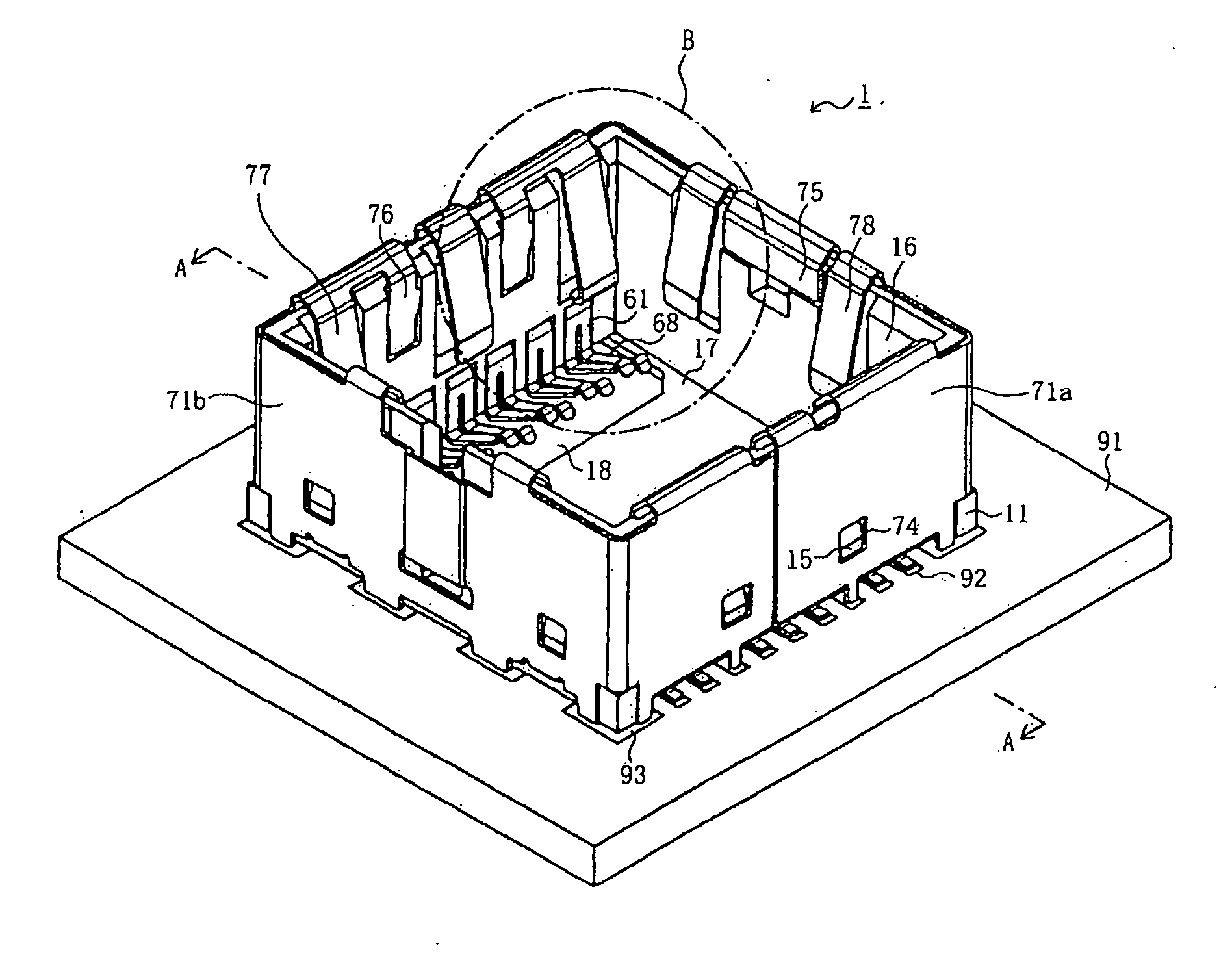
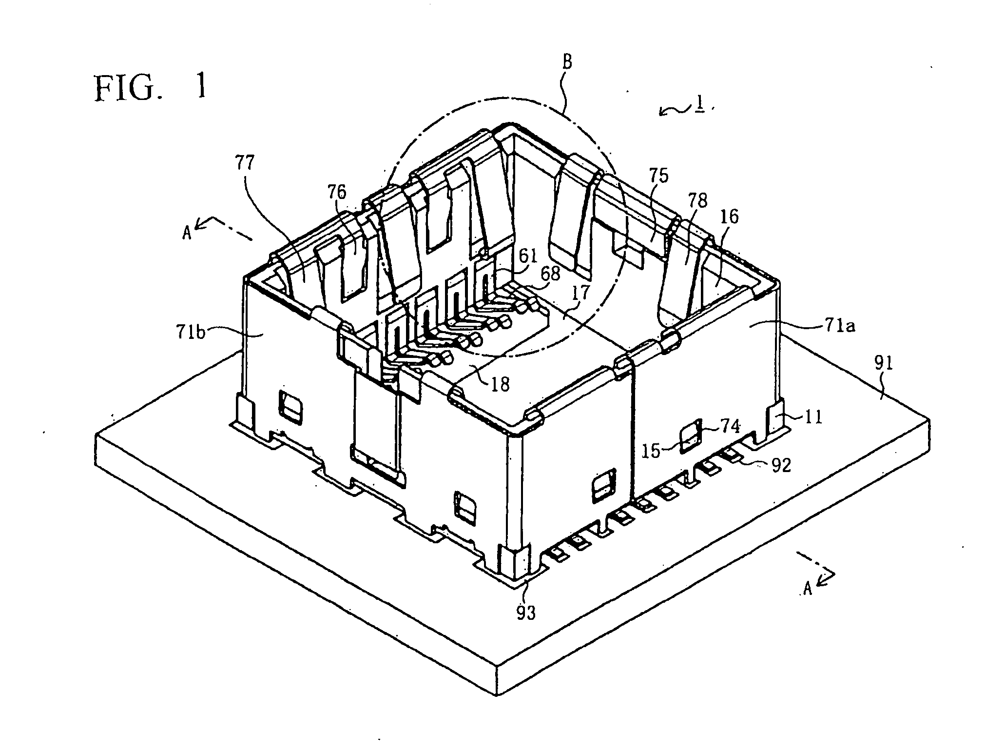
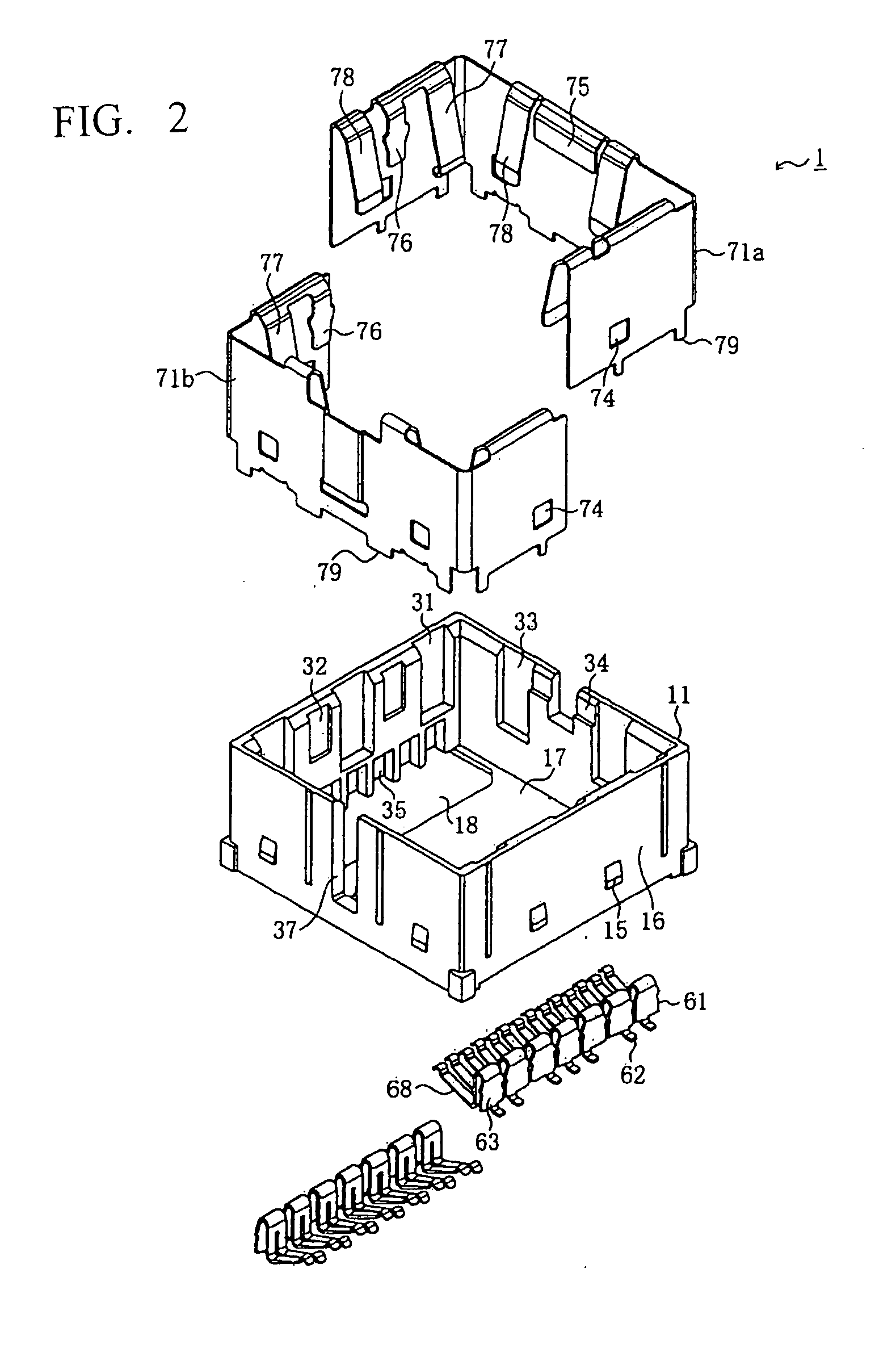
[0026]FIG. 1 is a perspective view of a socket according to an embodiment of the present invention, and reference numeral 1 denotes a socket for a module constructed in accordance with the principles of the present invention, which is used for electrically connecting a camera module 101 to a substrate 91. The camera module 101 preferably integrates an image pickup device such as a CCD, a CMOS image sensor, or the like and an optical element such as a lens. However, the module 101 may be any kind of module including a sensor module such as an infrared sensor or finger print reading sensor or acoustic element module such as a microphone. The socket 1 is used for mounting the module 101 in a small electronic device such as a cellular telephone, a PDA, or the like, but the socket 1 may also be used for mounting the module in a household electrical appliance such as a TV set, a washing machine, and a refrigerator, a monitor for security, and an automobile or the like. The socket 1 is mou...


PUM


Abstract

A method of tracking and acting on events related to the delivery of a mail piece is provided. An integrated record associated with an addressee of a mail piece is created. The mail piece is given a unique identifier, is associated with the addressee, and is placed in a mail stream with the date and nature of associated delivery events being recorded. After a predetermined delivery event occurs, a follow-up communication is transmitted to the addressee, and the date of this follow-up communication is recorded. The date of any response by the addressee to the follow-up communication is also recorded. To the integrated record associated with the addressee is added the date and nature of the delivery events associated with the mail piece, the date of the follow-up communication, and the date of any response by the addressee to the follow-up communication.

Description

BACKGROUND OF THE INVENTION[0001]The present invention relates generally to a socket for a module, and more particularly to a socket of improved connection reliability.[0002]Conventionally, sockets have been used to mount camera modules, which integrates an image pickup device such as a CCD (Charge Coupled Device), a CMOS (Complementary Metal Oxide Semiconductor) image sensor, or the like, and an optical element such as a lens, on a substrate of a small electronic device such as a cellular telephone, a PDA (Personal Digital Assistant), or the like. One such structure is described in Japanese Patent Application Laid-Open (Kokai) Publication No. 2003-91685).[0003]FIG. 10 is a cross-sectional view of such a conventional camera module socket.[0004]801 denotes the socket housing for a module, while 802 denotes the camera module, which is received in the socket housing 801. Also, two sets of locking devices 804 are provided on the inner surfaces of facing sidewalls of the socket housing 8...

Claims


Application Information

Patent Timeline
Patent Type & Authority Applications(United States)
IPC IPC(8): H01R13/62H04N5/225
CPCH01R13/2442H01R12/7076H01R33/74H01R33/76H01R13/639H04N23/00
Inventor MIZUMURA, AKINORI
Owner MOLEX INC
Learn More