Liquid crystal display device

a liquid crystal display and display device technology, applied in non-linear optics, instruments, optics, etc., can solve the problems flaws in displayed images, and conventional twisted nematic (tn) lcd devices have the disadvantage of narrow viewing angles, so as to prevent light leakage, increase contrast, and enhance light transmission rate

Active Publication Date: 2010-10-21
INNOLUX CORP
View PDF6 Cites 9 Cited by
  • Summary
  • Abstract
  • Description
  • Claims
  • Application Information

AI Technical Summary

Benefits of technology

[0032]Based on the above description, the objective of the LCD device of the present invention having no singular point is to enhance the light transmission rate by the optical rotation characteristics of the liquid crystal molecules and increase the contrast by the vertical alignment liquid crystal molecules, such that the LCD device of the present invention not only combines the advantages of both the conventional TN LCD device and the MVA LCD device but also prevents the light leakage problem occurred in the conventional TN LCD device.
[0033]To conclude, the LCD device of the present invention discloses that the first orienting structure is located on the outside of the display area and leads the liquid crystal molecules in the liquid crystal layer to incline toward the internal part of the pixel electrode. Compared to the conventional MVA LCD device, the LCD device of the present invention not only resolves the visual defect caused by the singular point but also achieves the wide viewing angle effect.

Problems solved by technology

In general, the conventional twisted nematic (TN) LCD device has the disadvantage of narrow viewing angles because of the structure and optical features of the liquid crystal molecules.
However, in the perspective of the light emitting surface or the light incident surface of the LCD device 1, the convex structures 113 and 123 may affect the aperture ratio for they are located within the pixel electrode of the pixel, and since the liquid crystal molecules between the convex structures 113 and 123 are not affected by the electric field and do not topple down, the singular point is generated in each pixel and this will cause flaws in the displayed image.

Method used


Image

  • Liquid crystal display device
  • Liquid crystal display device
  • Liquid crystal display device

Examples


Embodiment Construction

[0049]The present invention will be apparent from the following detailed description, which proceeds with reference to the accompanying drawings, wherein the same references relate to the same elements.

[0050]The following embodiments are presented based on a transmissive LCD device as well as a transflective LCD device.

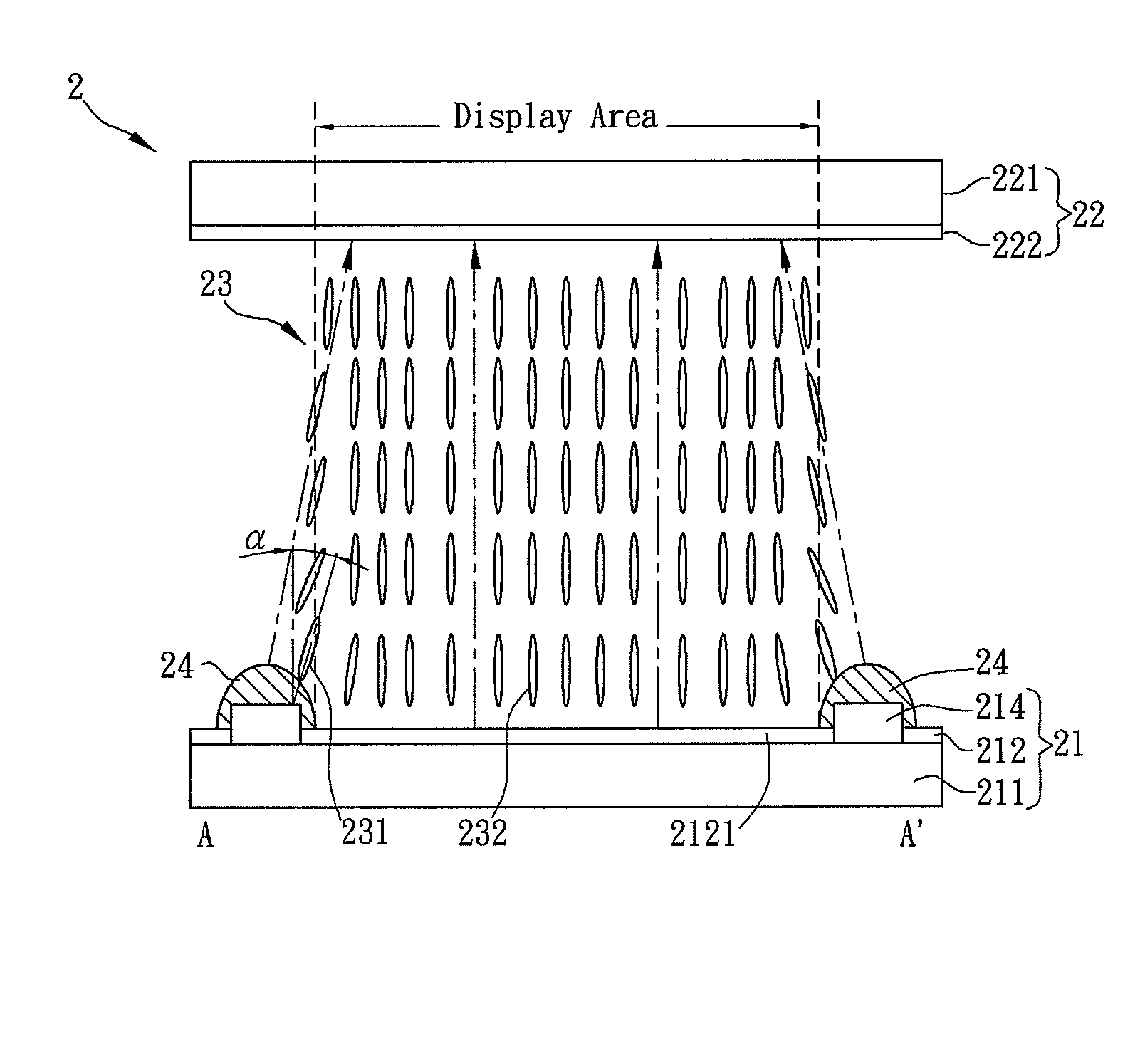
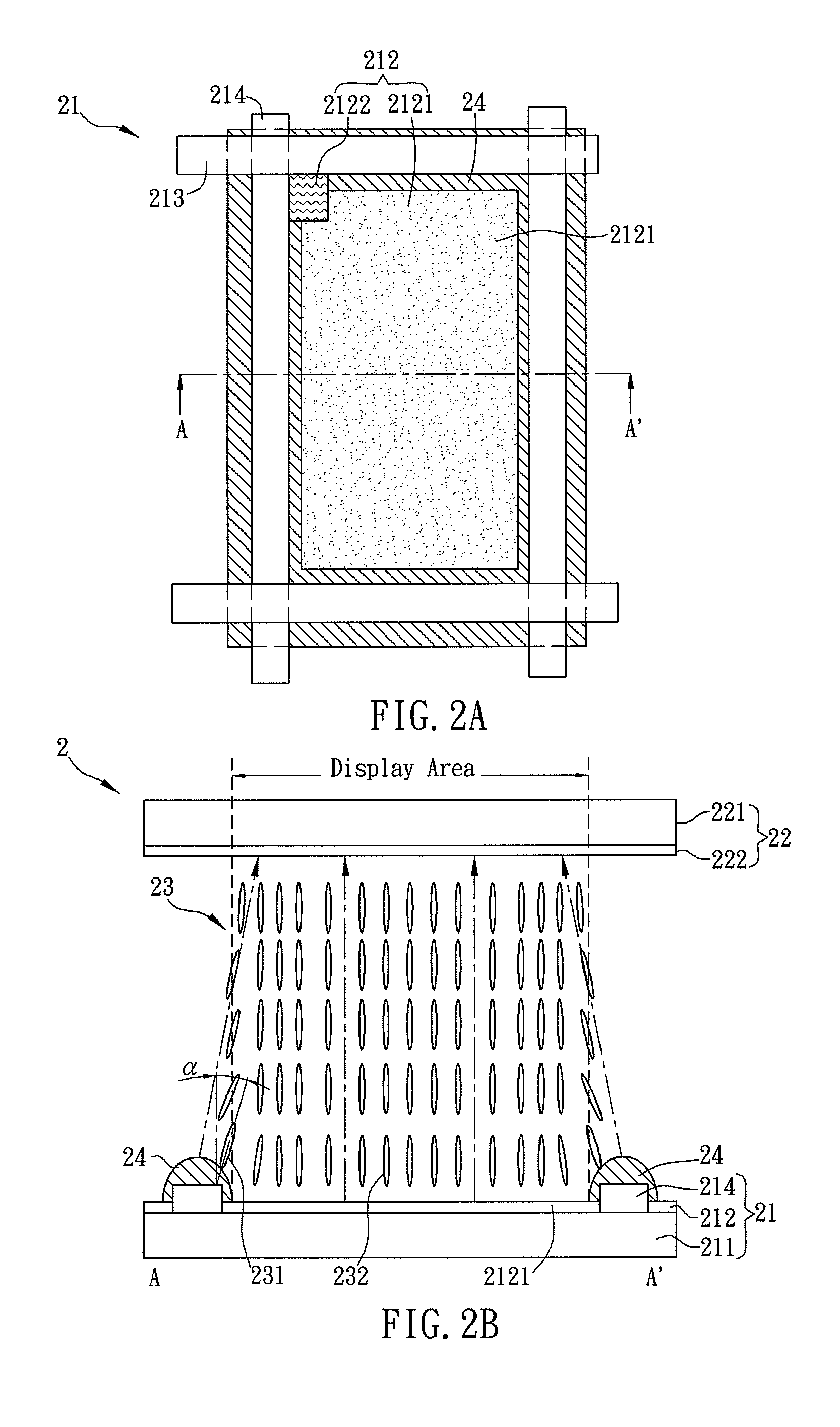
[0051]FIG. 2A is a top view of a LCD device 2 and FIG. 2B is a side view of the LCD device 2. As shown in FIGS. 2A and 2B, the LCD device 2, which has wide view angle and no singular point, includes a first substrate 21, a second substrate 22 disposed opposite and roughly parallel to the first substrate, a liquid crystal layer 23 disposed between the first substrate 21 and the second substrate 22, and a plurality of first orienting structures 24. An optical rotation material, such as a chiral material, is added to the liquid crystal layer 22. The liquid crystal molecules in the liquid crystal layer are rotated along an axis that is parallel to a normal line of the fir...


PUM

PropertyMeasurementUnit
inclined angleaaaaaaaaaa
angleaaaaaaaaaa

Abstract

This object aims to provide a liquid crystal display panel with good in viewing angle characteristic, and capable of carrying out a high brightness display. The liquid crystal display device includes a first substrate having at least one pixel unit and at least one first orienting structure, a second substrate disposed opposite to the first substrate, and a liquid crystal layer sealed between the first and second substrates and having negative dielectric anisotropy. The pixel unit includes a pixel electrode that is located in the display area, while the first orienting structure is located outside the display area. In addition, the liquid crystal layer contains an optical rotation material, and some of the liquid crystal molecules in the liquid crystal layer are inclined toward the internal part or the external part of the pixel unit by the first orienting structure.

Description

CROSS REFERENCE TO RELATED APPLICATIONS[0001]This Non-provisional application claims priority under 35 U.S.C. §119(a) on Patent Application No(s). 098113247 filed in Taiwan, Republic of China on Apr. 21, 2009, the entire contents of which are hereby incorporated by reference.BACKGROUND OF THE INVENTION[0002]1. Field of Invention[0003]The present invention is related to a liquid crystal display (LCD) device and, more particularly to a liquid crystal display device used in a wide viewing angle.[0004]2. Related Art[0005]In the liquid crystal display (LCD) device, the light transmission rate is controlled due to the different polarization effects or refraction effects induced by different alignments of the liquid crystal molecules, such that the LCD device can generate the desired image.[0006]In general, the conventional twisted nematic (TN) LCD device has the disadvantage of narrow viewing angles because of the structure and optical features of the liquid crystal molecules. To resolve ...

Claims


Application Information

Patent Timeline
Patent Type & Authority Applications(United States)
IPC IPC(8): G02F1/1337
CPCG02F2001/133742G02F1/133707G02F1/133742
Inventor PENG, CHENG-CHUNGSHEN, YURENFA, SHIH-HUNGWU, JIN-JEI
Owner INNOLUX CORP
Why Eureka
Try Eureka