Dispersion shift optical fiber
a technology of optical fiber and shift, applied in the field of shift optical fiber, can solve the problems of weak confluence effect of propagation mode, optical loss increasing at longer wavelengths, loss increasing with wavelength increase, etc., and achieve the effect of low dispersion slop
- Summary
- Abstract
- Description
- Claims
- Application Information
AI Technical Summary
Benefits of technology
Problems solved by technology
Method used
Image
Examples
embodiment 1
[EMBODIMENT 1]
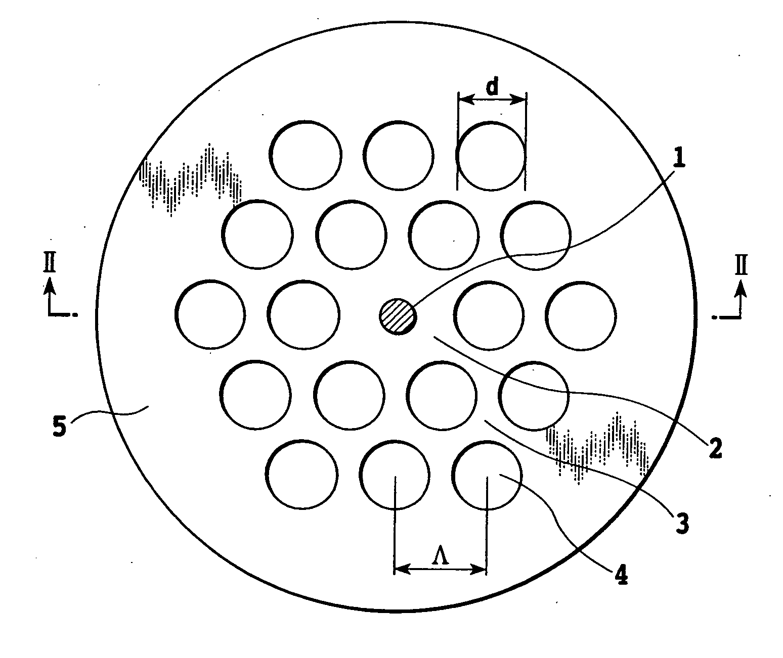
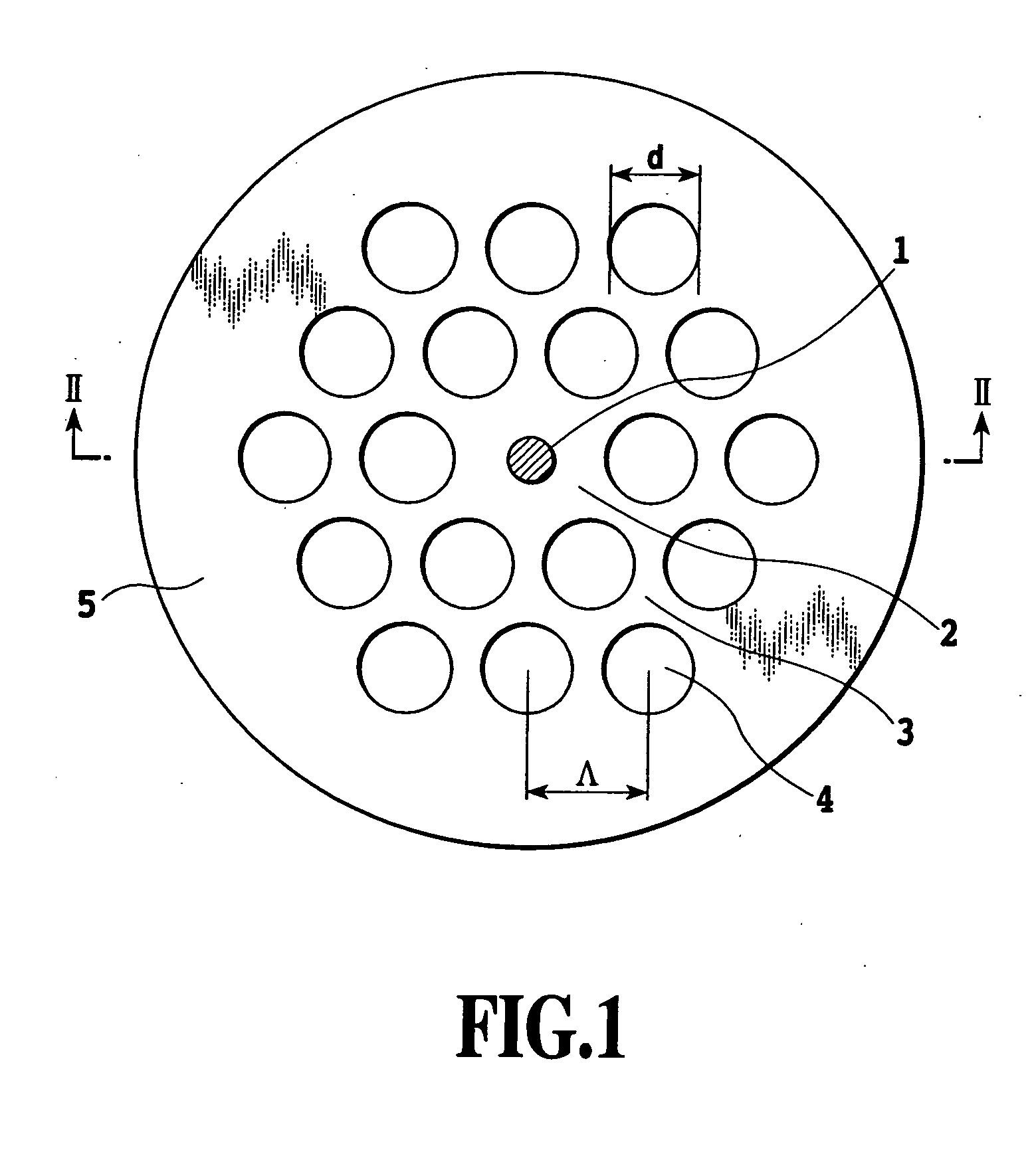
[0029]FIG. 1 is a cross-sectional view showing a structure of an embodiment 1 of the dispersion shifted optical fiber in accordance with the present invention.
[0030]In FIG. 1, the reference numeral 1 designates a heavily GeO2 doped core region “a”; 2 designates a core region “b” composed of pure SiO2 glass; 3 designates a cladding section surrounding the core region; and 5 designates a jacket section. The cladding section 3 has a lot of apertures 4 (called holes 4 from now on) extending in the longitudinal direction of the optical fiber.
[0031]The holes 4 in the cladding section 3 are not located at random, but have a honeycomb structure composed of regular hexagons which have a side length of Λ, and serve as a primitive lattice. Here, the diameter of the holes 4 is represented by d.
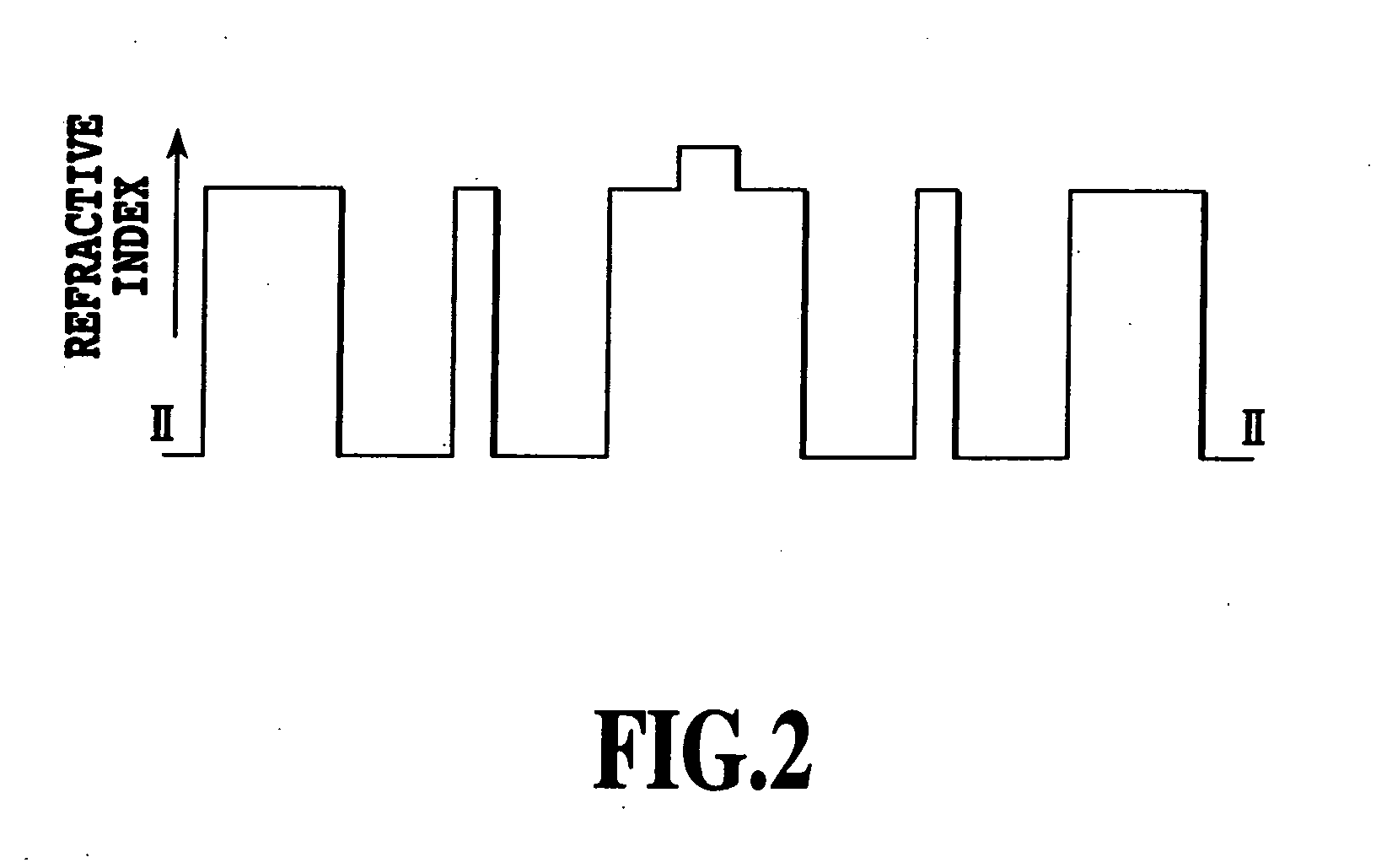
[0032]FIG. 2 is a diagram showing the refractive index distribution of the cross-section along a line II-II of FIG. 1. The lowest level represents the refractive index of the holes (n=1). Th...
embodiment 2
[EMBODIMENT 2]
[0040]In the present embodiment 2 in accordance with the present invention, the refractive index distribution of the core section “a”, which is the stepwise refractive index distribution in the embodiment 1, is made double cladding type or triple cladding type. FIGS. 4A and 4B show examples of the refractive index distribution: FIG. 4A shows double cladding type refractive index distribution; and FIG. 4B shows triple cladding type refractive index distribution. Except for the holes 4, the refractive index distribution of FIGS. 4A and 4B is equivalent to the refractive index distribution of a well-known dispersion compensated fiber. The refractive index distribution can implement an optical fiber with large normal dispersion.
[0041]Surrounding the core regions 1 and 2, which have the foregoing refractive index distribution, with the highly regularly arranged holes 4 can compensate for the normal dispersion caused by the contribution of the core region by the anomalous di...
embodiment 3
[EMBODIMENT 3]
[0046]FIG. 6 is a view showing the embodiment 3 in accordance with the present invention. In FIG. 6, the reference numeral 11 designates a core region “a” that is heavily doped with GeO2; 12 designates a core region “b” composed of pure SiO2; 13 designates a cladding section; 14a designates a hole “a”; 14b designates a hole “b”; and 15 designates a jacket section.
[0047]The holes “b” are placed in such a manner that they are adjacent to the core region, and has two-fold axial symmetry. The diameter of the holes b is made greater or less than that of the holes “a”.
[0048]FIG. 7 is a diagram showing the refractive index distribution of the cross-section along a line VII-VII of FIG. 6. That the holes “a” and “b” have different diameters brings about anisotropy in the equivalent refractive indices in the x and y axis directions of FIG. 7. As a result, the propagation mode polarized at the x and y directions, has large birefringence. The large birefringence reduces the polari...
PUM
 Abstract
Description
Claims
Application Information
 - R&D
- Intellectual Property
- Life Sciences
- Materials
- Tech Scout
- Unparalleled Data Quality
- Higher Quality Content
- 60% Fewer Hallucinations
Browse by: Latest US Patents, China's latest patents, Technical Efficacy Thesaurus, Application Domain, Technology Topic, Popular Technical Reports.
© 2025 PatSnap. All rights reserved.Legal|Privacy policy|Modern Slavery Act Transparency Statement|Sitemap|About US| Contact US: help@patsnap.com


