
Optical fibre and optical communication system using it

A technology of optical fiber and reference layer, which is applied in the field of optical transmission system, can solve problems such as interference, and achieve the effect of low nonlinearity and low dispersion slope

Inactive Publication Date: 2004-12-01
FURUKAWA ELECTRIC CO LTD
View PDF0 Cites 0 Cited by
  • Summary
  • Abstract
  • Description
  • Claims
  • Application Information

AI Technical Summary

Problems solved by technology

[0013] However, according to the existing researched optical fiber for wavelength division multiplexing transmission, the wavelength dispersion at 1.55μm wavelength is about -4ps / nm / km to +6ps / nm / km, and its dispersion slope is 0.05ps / nm 2 A value of / km or more, therefore, the zero dispersion wavelength is a value of 1.4 μm or longer, so as to cause interference of excitation light with a wavelength of about 1.4 μm and four-wave mixing, etc.

Method used

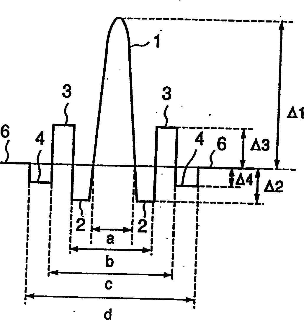

Image

  • Optical fibre and optical communication system using it
  • Optical fibre and optical communication system using it
  • Optical fibre and optical communication system using it

Examples


Embodiment Construction

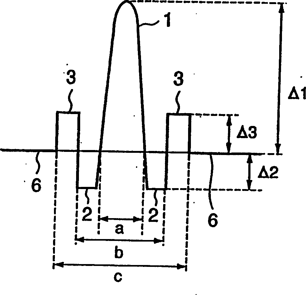
[0025] Specific embodiments of the present invention will be described below based on the accompanying drawings. Figure 1A A cross-sectional view showing the refractive index distribution in the optical fiber according to the first embodiment of the present invention. The refractive index distribution diagram as an optical fiber can be made as the refractive index distribution in various modes, but, in the first embodiment, adopt such as Figure 1A The refractive index profile shown. The structure of this refractive index distribution is relatively simple, and it is easy to design and control in the refractive index structure.

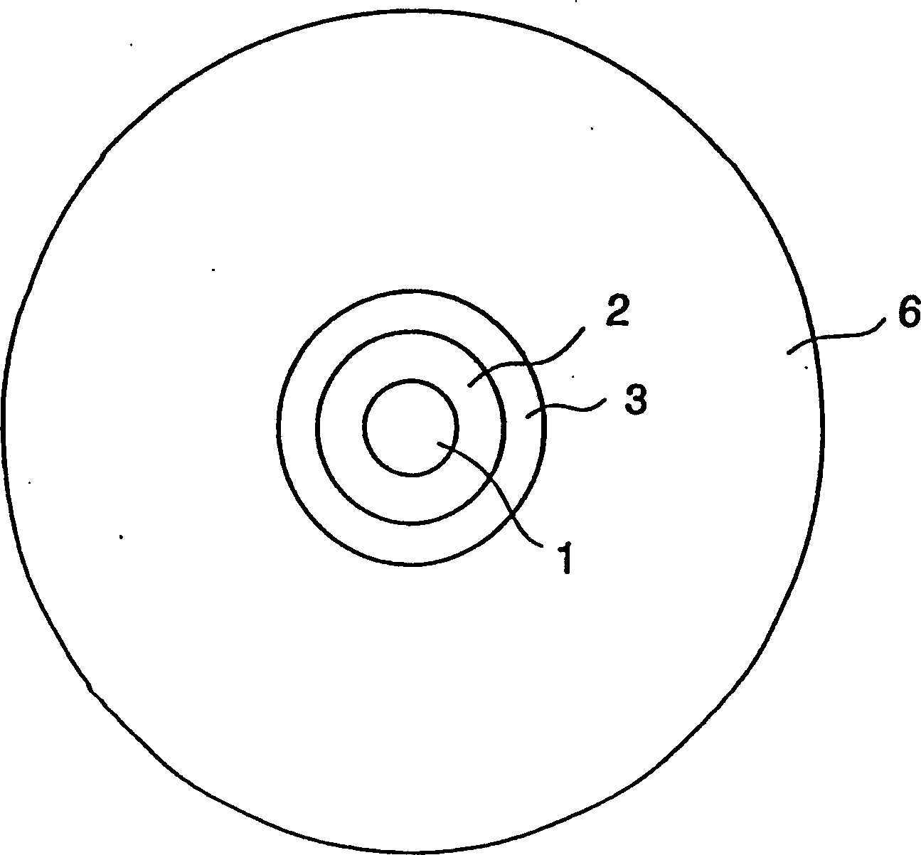
[0026] The optical fiber of the first embodiment has multiple (here four) glass layers (first glass layer 1, second glass layer 2, third glass layer 3 and reference layer 6) of different compositions adjacent to each other. like Figure 1B As shown, these glass layers are concentric. The reference layer 6 as the outermost layer is a layer constituti...


PUM


Abstract

The present invention resides in an optical fiber able to form an optical transmitting line for wavelength division multiplexing transmission in a wavelength band of 1.5 mum using a Raman amplifier, and an optical communication system using this optical fiber. The optical fiber has an effective core area from 40 mum<2 >to 60 mum<2 >in a set wavelength band of at least one portion of a wavelength band of 1.5 mum; a dispersion value from 4 to 10 ps / nm / km at a wavelength of 1.55 mum; a dispersion slope set to a positive value equal to or smaller than 0.04 ps / nm<2> / km in a wavelength band of 1.55 mum; and a zero dispersion wavelength equal to or smaller than 1.4 mum. Further, a cutoff wavelength is set to be equal to or smaller than 1.5 mum at a length of 2 m, and a bending loss is set to be equal to or smaller than 5 dB / m at a diameter of 20 mm in the wavelength band of 1.5 mum. In a refractive index profile of the optical fiber, for example, a relative refractive index difference Delta1 of a first glass layer as an innermost layer with respect to a reference layer, and a relative refractive index difference Delta3 of the refractive index of a third glass layer as a third layer from an inner side with respect to the reference layer are set to be positive. Further, a relative refractive index difference Delta2 of a second glass layer as a second layer from the inner side with respect to the reference layer is set to be negative.

Description

technical field [0001] The present invention relates to an optical fiber for optical transmission such as wavelength division multiplexing (WDM) transmission, etc., such as optical transmission in a long band such as 1.5 microns, and an optical transmission system using this optical fiber. Background technique [0002] With the development of the information society, the communication information capacity tends to increase dramatically. When such information increases, wavelength division multiplexing transmission (WDM transmission) and time division multiplexing transmission (TDM transmission) are attracting attention. This wavelength-division multiplexing transmission uses one optical fiber to transmit signals of multiple wavelengths, and is therefore an optical transmission method suitable for large-capacity and high-bit-rate transmission. Currently working on research and development of wavelength division multiplexing transmission technology. [0003] It is currently ...

Claims


Application Information

Patent Timeline
Patent Type & Authority Patents(China)
IPC IPC(8): G02B6/02G02B1/00G02B6/00G02B6/036H04J14/02
CPCG02B6/02009G02B6/02242C03B2203/36G02B6/03666G02B6/02271G02B6/0281C03B2203/22G02B6/03644G02B6/03688G02B6/00
Inventor 武笠和则熊野尚美
Owner FURUKAWA ELECTRIC CO LTD
Learn More