Automatic transport loading system and method

a technology of automatic transportation and loading system, applied in the direction of process and machine control, distance measurement, instruments, etc., can solve the problems of variable position of the transport in relation, inability to track the direction of the system, and inability to use the system effectively, efficiently and accurately, so as to slow down the movement of the agv. the effect of speeding up the movemen

Active Publication Date: 2010-10-21
JERVIS B WEBB INT CO
View PDF99 Cites 62 Cited by
  • Summary
  • Abstract
  • Description
  • Claims
  • Application Information

AI Technical Summary

Benefits of technology

[0013]In view of the above, a need exists for an AGV design that effectively, efficiently, and accurately uses guidance systems to automatically load and unload a transport. More particularly, the present invention is directed to an AGV design that is capable of loading and unloading a transport that may not be in its expected position as well as compensate or adjust for any variations between the expected position and actual position of the AGV without the need for continuous updates that may slow down movement an AGV while placing or retrieving loads in the transport.
[0016]In another embodiment of the present invention, the AGV scans the position of the transport to determine if the floor transport is vertically offset or if the floor of the transport is angled relative to the floor of the loading bay or dock ramp. When the last AGV places the last load, or at times one of the last few loads inward of the door, the AGV adjusts its forks angularly relative to the AGV to compensate for any angular or vertical offset, such that the AGV forks smoothly enter or exit the pallet pockets without changing the position of the placed load. Therefore, the system actively measures the position of the transport and compensates the position of the AGV forks on the last couple of loads placed inward of the door of the transport.
[0017]In another embodiment, the system uses regular, but not continuous, updates within the transport to check that the expected location of the AGV matches the actual location of the AGV. More specifically, the laser sensor or other sensors may at regular intervals scan the interior of the transport and update the location of the AGV within the transport, if necessary. Regular updates minimize the processing time needed to determine position, yet ensure that the guidance system on the AGV accurately determines the position of the AGV within the transport.

Problems solved by technology

For example, inertial guidance is susceptible to tracking errors, where the travel distance and direction measured by the AGV differs from the actual distance and direction of travel.
This type of system is susceptible to obstruction of markers and, most notably, requires markers to be present in any environment of travel.
One difficulty associated with the automatic loading and unloading of a transport is the variable position of the transport in relation to the loading dock.
This manual positioning results in an unknown variability in the position of the transport.
As a driver positions a transport, such as a trailer at the loading dock, he or she may be unable to perfectly square the trailer with the dock door.
Since the angle is unknown and can vary at each positioning at the dock, an AGV cannot effectively guide and deliver loads in the trailer, unless the skew is adjusted or the AGV has the capability of detecting and compensating for this trailer skew.
The prior art has addressed this problem by using skid plates to position the transport in relation to the loading docks, however this is a costly and inefficient process.
In loading wider loads by AGVs, an offset as little as one inch may cause problems during the loading process.
Many variances in the positioning of the transport, as well as between the transport and the loading dock, may cause difficulties in the AGV loading the transport and, in particular, the end of the transport.
The difficulty associated with automatic loading and unloading of a transport is that the AGV must be able to overcome the difference in height between the transport and the dock.
Furthermore, the height of a particular transport is not static; as the transport is loaded the suspension will compress, resulting in a change in the height of the transport.
Any contact between the load and the transport will cause problems in the loading of the transport.
The prior art has addressed this problem by using hydraulic or other types of jacks to stabilize and level the transport; however, this is another costly and inefficient process.
The variability in position of the transport may prohibit the automatic loading of the transport, and almost certainly will reduce its efficiency.
Other problems may also occur, which cause differences between the actual location of the AGV and the expected position, as determined by the guidance system.
One cause of such problems is slick surfaces on which the AGV travels, including the loading bay floor, dock ramp, and transport floor.
The transports may be used at a variety of facilities and, in some circumstances, loading equipment may leak slippery substances such as oil, hydraulic fluid, and other fluids onto the transport floor.
As expected, any differences between the expected position and actual position may cause errors in placement of loads, undesirable contact of the AGV or load with transport walls, or future guidance errors.
One problem with this system is that it may slow down the loading and unloading of transports, as the AGV must constantly measure and adjust for any variations.
The transition between the two may require a steep incline or decline between dock and transport, which can cause guidance difficulties and end-of-trailer loading difficulties.
For example, an AGV that uses a laser guidance system may lose the target as it moves up an incline or down a decline, due to the fact that the laser will be pointing either above or below the target.
The difficulty with end-of-trailer loading for the above described transport and transport loading area facilities is that if the AGV is not at an equal angle to the transport floor, such as the majority of the AGV being situated on the dock ramp or loading facility floor, it may be difficult for the AGV to lower its load to the transport floor and then easily remove its forks from the pallet pockets.
More specifically, if the transport floor is not aligned both vertically and angularly with the loading facility floor or dock ramp, it may be difficult to withdraw the forks from the pockets on the pallets as the tip of the fork engages one of the top and bottom, and the portion of the fork nearest to the AGV engages the other of the top and bottom.
The dock ramp is typically formed from steel and may become slippery, causing errors with the guidance system.

Method used


Image

  • Automatic transport loading system and method
  • Automatic transport loading system and method
  • Automatic transport loading system and method

Examples


Embodiment Construction

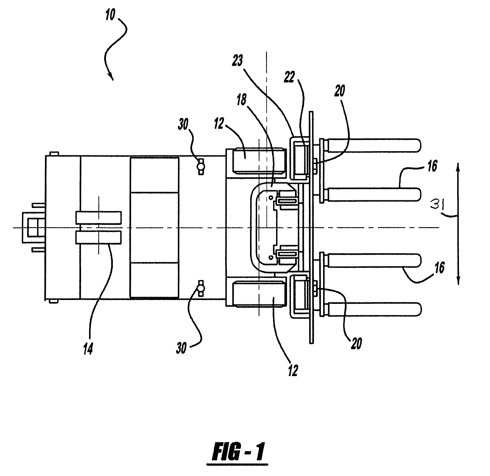
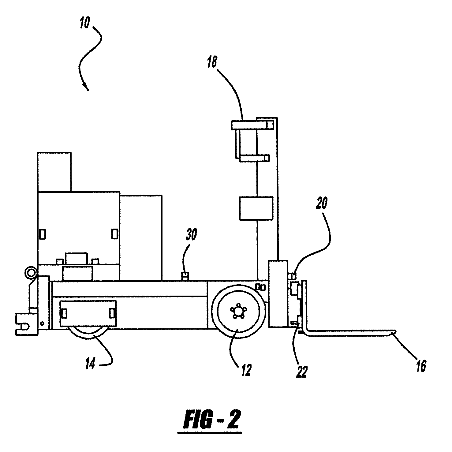
[0031]An automated guided vehicle 10 according to the present invention is illustrated and described with reference to the figures. It should be appreciated that the applications for the automatic loading and unloading of a transport according to the present invention may be used in a variety of applications beyond the illustrated AGV. For example, the present invention may be used with automated guided vehicles of a variety of configurations, as well as other material handling vehicles.

[0032]The AGV 10 includes a steering and drive mechanism that is used to propel and steer the AGV 10. In the illustrations shown, the steering and drive mechanism comprises drive wheels 12 and steerable wheel 14 that are coupled with a guidance system and used to propel and steer the AGV 10. The guidance system turns the steerable wheel 14 as the AGV 10 is propelled, thus steering the AGV 10. Additionally, the drive wheels 12 are preferably dual drive wheels wired in series to create an electrical di...


PUM


Abstract

A method and system for automatically loading and unloading a transport is disclosed. A guidance system follows a travel path to a position near the transport and then a sensor profiles a transport so that a transport path is determined for an AGV to follow into the transport to place a load and for exiting the transport upon placement of the load.

Description

CROSS-REFERENCE TO RELATED APPLICATIONS[0001]This application claims priority to and is a continuation-in-part of U.S. patent application Ser. No. 11 / 766,646, filed Jun. 21, 2007, which is a continuation-in-part of U.S. patent application Ser. No. 11 / 119,588, filed May 2, 2005, which claims the benefit of U.S. Provisional Application No. 60 / 567,729, filed May 3, 2004, the entire disclosure of these applications being considered part of the disclosure of this application and hereby incorporated by reference.BACKGROUND OF THE INVENTION[0002]The present invention is generally directed to material handling vehicles and, more particularly, to an automatic guided vehicle that is capable of automatically loading and unloading a transport, including loads near the end of the transport with minimal interference, even when the transport floor is vertically offset from or angled relative to the floor of the loading bay or a dock ramp extending between the transport floor and the loading bay fl...

Claims


Application Information

Patent Timeline
Patent Type & Authority Applications(United States)
IPC IPC(8): B65G67/04G06F19/00
CPCB66F9/063G01C22/00G05D2201/0216G05D1/0272G05D1/024
Inventor CHILSON, GERALD EDWARDROSS, WAYNE DAVID
Owner JERVIS B WEBB INT CO
Why Eureka
Try Eureka