Self-Anchoring MEMS Intrafascicular Neural Electrode

a neural electrode and self-anchoring technology, applied in the field of neurology, can solve the problems of electrode placement, painful stimulation, and awkward us

Inactive Publication Date: 2010-10-21
ARIZONA STATE UNIVERSITY
View PDF30 Cites 44 Cited by
  • Summary
  • Abstract
  • Description
  • Claims
  • Application Information

AI Technical Summary

Problems solved by technology

The disadvantages of surface (skin) stimulation include that it is awkward to use and requires that electrodes be placed in the proper location upon every use.
Additionally, large currents must be applied with these systems and in people having partial neural sensation, for example, persons with incomplete spinal cord injury, such stimulation can be painful.
For example, glass micropipette electrodes can be used as suction electrodes to record and monitor neural activity, however these electr

Method used


Image

  • Self-Anchoring MEMS Intrafascicular Neural Electrode
  • Self-Anchoring MEMS Intrafascicular Neural Electrode
  • Self-Anchoring MEMS Intrafascicular Neural Electrode

Examples


example 1

Design and Manufacture of a Prototype Intrafascicular Neural Electrode

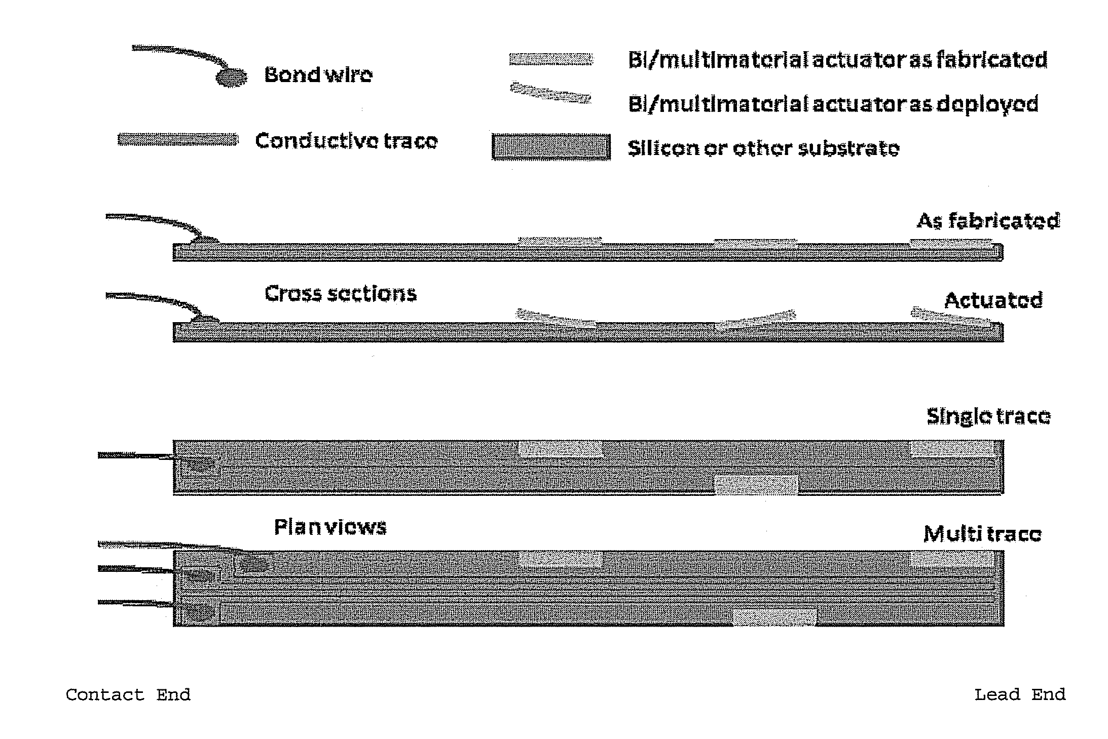
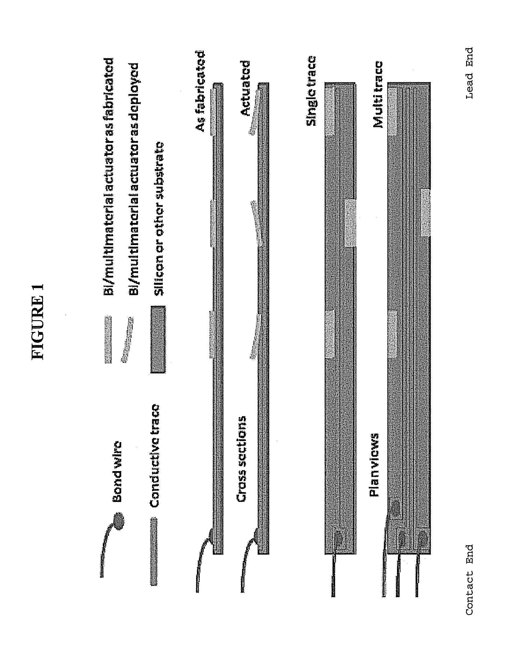
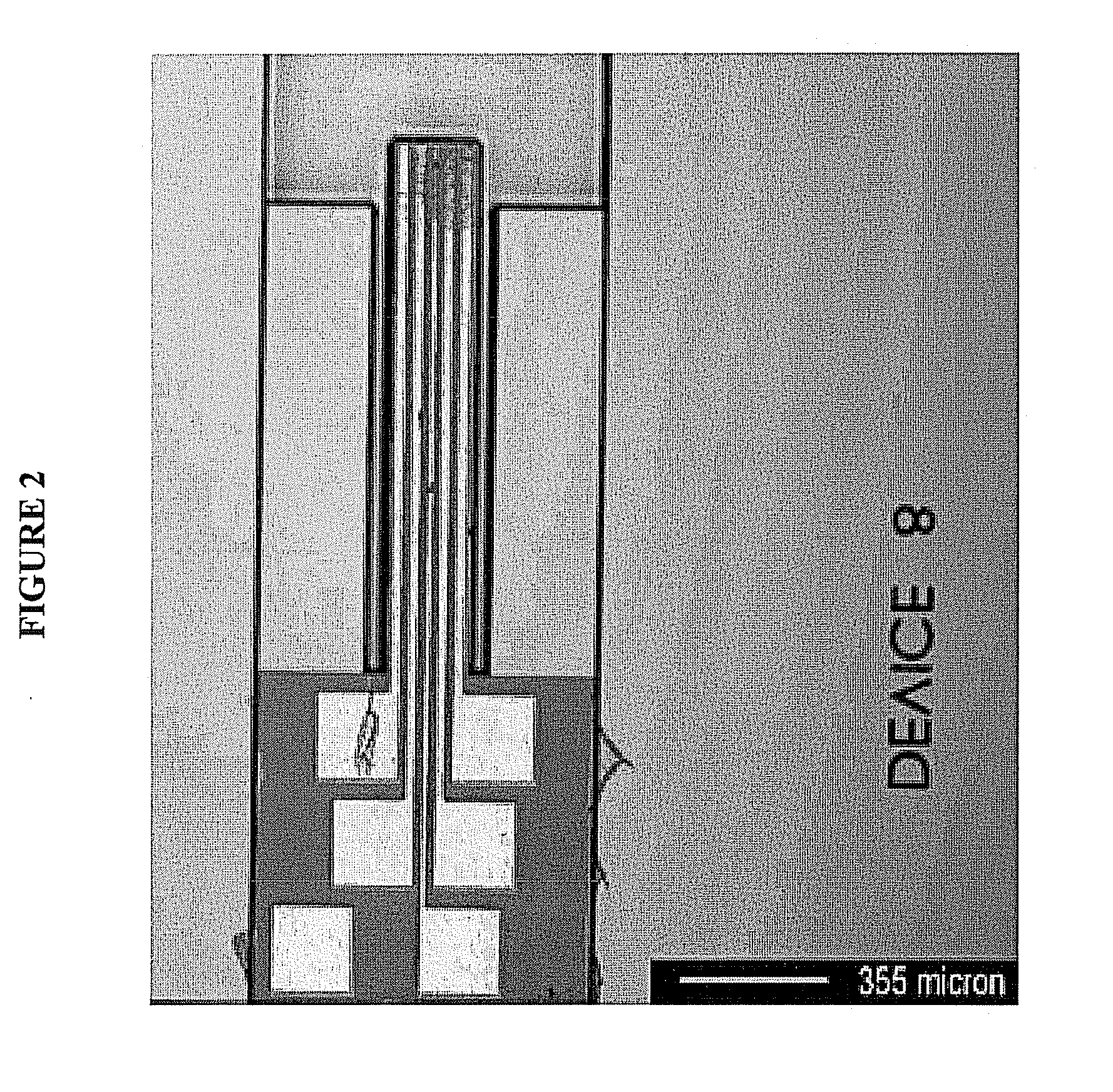
[0089]Standard MEMS processes are used to construct a series of the neural electrodes of the invention, such as wafer level batch microfabrication methods described in Madou, M., Fundamentals of Microfabrication, CRC Press 1997, ISBN 0-8493-9451-1; Kovacs, G., Micromachined Transducers Sourcebook, McGraw-Hill 1998, ISBN 0-0729-0722-3; Senturia, S. D., Microsystem Design, Kluwer 2000, ISBN 0-7923-7246-8; and Sze, S. M. ed., Semiconductor Sensors, Wiley 1994, ISBN 0-4715-4609-7. Known processes employing oxidation, structural polysilicon growth and metal deposition are combined to generate the stem and barb self-anchoring configuration, as well as the location and design of the conductive traces. A standard single crystal silicon wafer having dimensions of 0.5 mm (thickness) and 100 mm (length) allows for the production of several thousand electrodes of the invention. Depending on the desired dimension of the electr...

example 2

Characterization of the Thermal and Mechanical Self-Anchoring System

[0091]A set of intrafascicular electrodes having a wide variation in dimensional parameters, number and configuration of barb structures, and number and location of conductive traces are analyzed to determine deflections and forces as a function of temperature for the variously configured electrodes. A controlled temperature deionized water bath, followed by a saline bath determines the device “deflectance temperature” within the 5°-30° C. range. The displacements induced by the temperature change are measured using optical microscopy and optical interferometry. The force calculations are determined from the materials properties (modulus) that are extracted form non-device portions of the processed wafers and the dimensions observed by optical microscopy.

example 3

Self-Anchoring Evaluation Using Animal Nerve Tissue

[0092]The self-anchoring capabilities of the intrafascicular neural electrodes are tested using neural tissue derived from animals. American bullfrogs are anesthetized in a bath of 1-3% MS-222 solution for about 20-30 min. The anesthetized frogs are decerebrated, the spinal cord is pithed, and the hindleg peripheral nerves from are removed. The peripheral nerve(s) are stretched to various tensions so that performance of the self-anchoring mechanism is characterized based on device placement under given tensions.

[0093]Based on the results from the anchoring and performance studies using frog nerve tissue, experiments are designed using rodent nerve tissue. Both fixed and fresh samples of rat (female Long-Evans) nerve tissue from the phrenic, sciatic, and tibial nerves, as well as lumbosacral nerve roots are used to develop optimized operating conditions and device design.


PUM


Abstract

The present invention provides a self anchoring electrode for recording, measuring and/or stimulating nerve activity in nerves and/or nerve fascicles of the peripheral nervous system, and methods for using such a self anchoring electrode.

Description

CROSS REFERENCE TO RELATED APPLICATIONS[0001]This application claims priority to U.S. Provisional Application Ser. No. 60 / 950,643, filed Jul. 19, 2007, and to U.S. Provisional Application Ser. No. 60 / 991,958, filed Dec. 3, 2007, each of which is incorporated by reference herein in its entirety.STATEMENT OF GOVERNMENT INTEREST[0002]This invention was made with government support under grant number EB003629 awarded by the National Institute of Health. The government has certain rights in the invention.BACKGROUND OF THE INVENTION[0003]In recent years advances have been made in the field of neurobiology, in particular in the development of neuroprosthetic devices for motor control. An important aspect in the further advancement of the field and, for example, the control systems for neuroprosthetic devices, will be the ability to obtain stable spatiotemporally distributed recording of neural activity chronically. While the ability to record neural activity plays a critical role in develo...

Claims


Application Information

Patent Timeline
IPC IPC(8): A61B5/04C12N13/00H01R43/00A61N1/05
CPCA61B5/04001A61B5/6882A61N1/0558A61B2562/125A61B2562/028A61B5/4064A61B5/4076A61B5/24
Inventor JUNG, RANUPHILLIPS, STEPHEN M.ABBAS, JAMES J.
Owner ARIZONA STATE UNIVERSITY
Why Eureka
Try Eureka