Position control method, position control device, and medium storage device having disturbance suppression function

a position control and disturbance suppression technology, applied in the direction of program control, electric controllers, instruments, etc., can solve the problems of affecting positioning accuracy, unable to sufficiently suppress external vibrations, and unable to accurately control the position, so as to achieve accurate calibration and accurate position control

Active Publication Date: 2010-10-21
KK TOSHIBA
View PDF22 Cites 16 Cited by
  • Summary
  • Abstract
  • Description
  • Claims
  • Application Information

AI Technical Summary

Benefits of technology

[0014]With the foregoing in view, it is an object of the present invention to provide a position control method, position control device, and medium storage device for accurately calibrating the open loop gain in a position control system using the disturbance adaptive control.
[0015]It is another object of the present invention to provide a position control method, position control device, and medium storage device for accurately calibrating the open loop gain even while disturbance is being applied.
[0016]It is still another object of the present invention to provide a position control method, position control device, and medium storage device for accurately calibrating the open loop gain, even if the disturbance suppression frequency is set from the outside.
[0017]It is still another object of the present invention to provide a position control method, position control device, and medium storage device for accurately calibrating the open loop gain, even if the position control system adapts to disturbance suppression frequencies in a wide range.
[0027]Because of disturbance suppression control, open loop gain is calibrated using a target gain according to a disturbance frequency, even if a loop characteristic of a feedback controller changes, so the open loop gain can be calibrated without interrupting the disturbance suppression control. Therefore the open loop gain can be accurately calibrated without being affected by disturbance, and accurate position control is possible.

Problems solved by technology

In this position control, it is known that disturbance affects positioning accuracy.
In this case, the external vibrations cannot be sufficiently suppressed and positioning accuracy drops since the adaptive control is stopped.
As a result, accuracy of gain adjustment drops.
In other words, in the case of such a position control system as an adaptive control system, disturbance is suppressed by changing the loop characteristic according to disturbance, so it is difficult to accurately calibrate the open loop gain of the control system using prior art.
Particularly if suppression width is taken wide or if disturbance in a high frequency area is suppressed to meet the recent demand for adapting a wide range of disturbance frequencies, the original characteristics of the controller are influenced, so it is more difficult to calibrate gain accurately.

Method used


Image

  • Position control method, position control device, and medium storage device having disturbance suppression function
  • Position control method, position control device, and medium storage device having disturbance suppression function
  • Position control method, position control device, and medium storage device having disturbance suppression function

Examples


first embodiment

of Position Control System

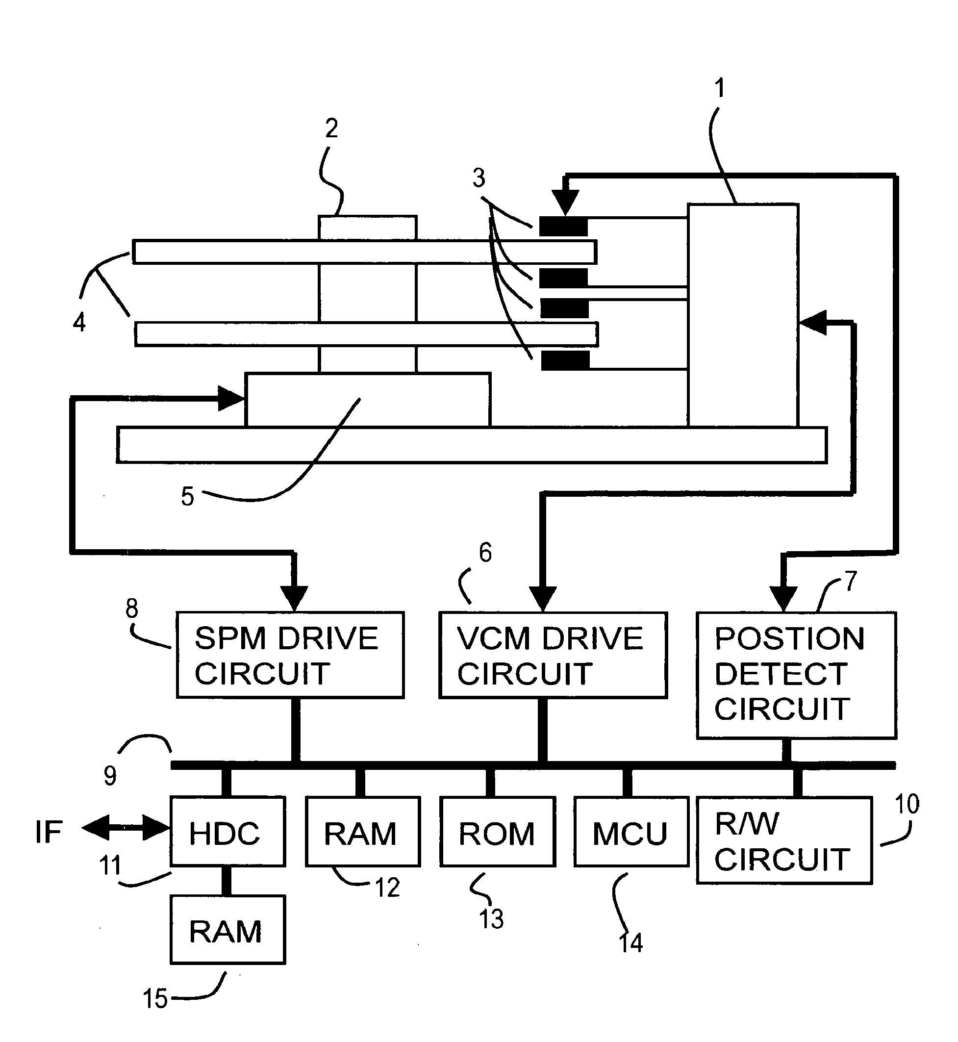
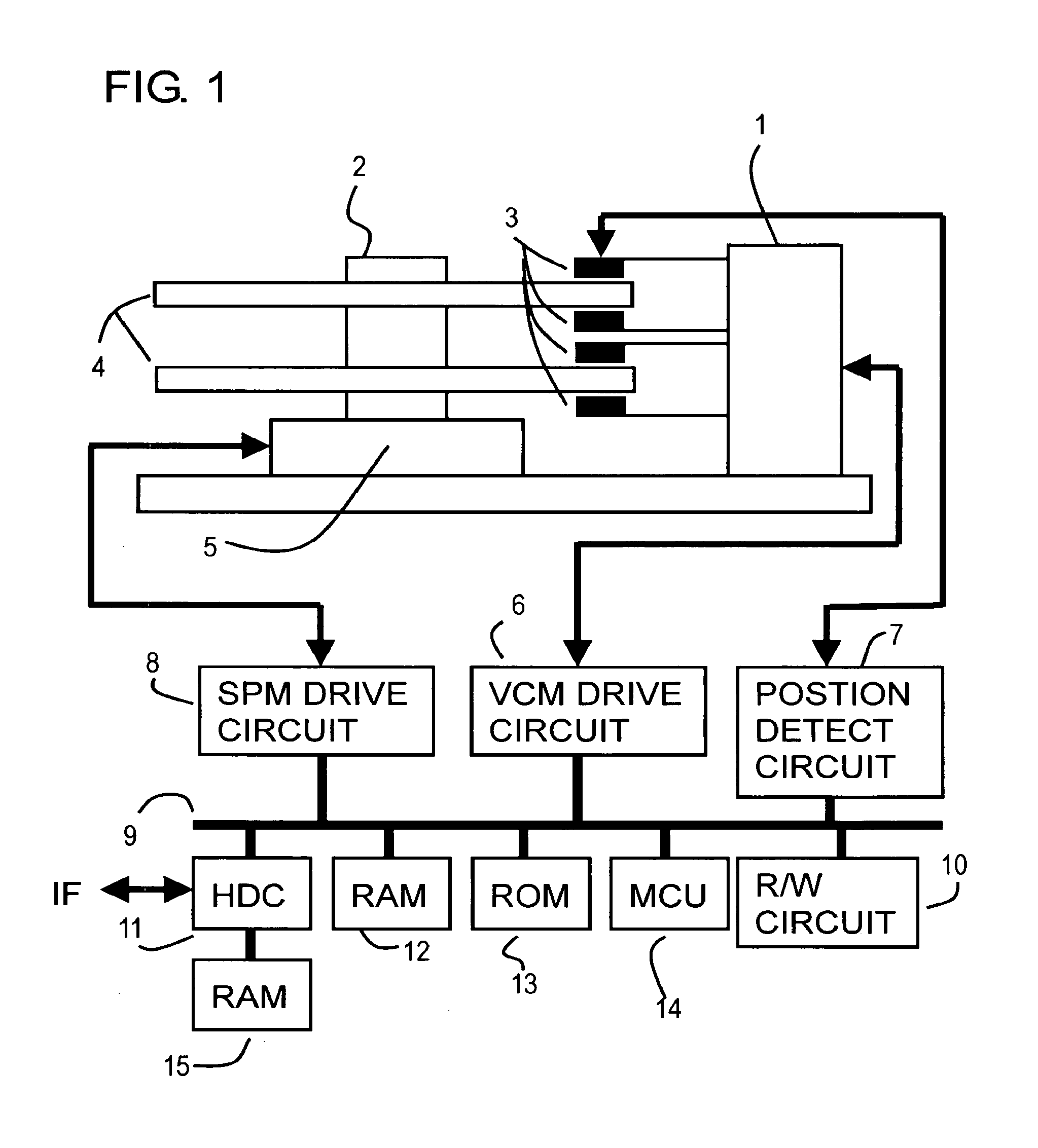
[0061]FIG. 4 is a block diagram depicting a first embodiment of the position control system of the present invention, and is a block diagram of a position control system for suppressing disturbance which the MCU 14 in FIG. 1 executes. FIG. 5 shows the target gain table in FIG. 4, and FIG. 6 and FIG. 7 are characteristic diagrams of the disturbance adaptive control in FIG. 4.

[0062]The position control system in FIG. 4 controls a disturbance suppression compensation function of a controller which is set from the outside, or according to a detected disturbance frequency Fdist. A gain adjustment function is added to this position control system. An error computing block 24 subtracts an observation position (current position) ‘y’ from a target position ‘r’ to compute a position error ‘e’.

[0063]According to the position error ‘e’, a controller 20 computes a drive instruction value ‘u’ of a plant 22 (1, 3) to make the position error ‘e’. The controller 20 computes...

second embodiment

of Position Control System

[0081]FIG. 10 is a block diagram depicting a second embodiment of the position control system of the present invention. In FIG. 10, composing elements the same as those in FIG. 4 are denoted with the same reference symbols.

[0082]Just like FIG. 4, an error computing block 24 subtracts an observation position (current position) y from the target position r to compute a position error e. A controller 20 computes, according to position the error e, a drive instruction value u of a plant 22 (1, 3) to make the position error e zero. The controller 20 computes the drive instruction value u by a known PID control, PI control+LeadLag, and observer control, for example.

[0083]A gain multiplication block 26 multiplies the drive instruction value u from the controller 20 by a gain which is set (open loop gain), and outputs the result. A power amplifier, which is not illustrated, converts this output into a drive current I of the plant 22 (1, 3), and drives the plant 22 ...

third embodiment

[0092]FIG. 12 is a block diagram depicting a third embodiment of the position control system of the present invention, FIG. 13 is a block diagram when the control system in FIG. 12 is constructed with a current observer, and FIG. 14 is the parameter table in FIG. 13.

[0093]FIG. 12 shows a position control system for detecting a disturbance frequency and suppressing the disturbance by adaptive control, and in FIG. 12, composing elements the same as those in FIG. 4 are denoted with the same reference symbols.

[0094]In other words, an error computing block 24 subtracts an observation position (current position) ‘y’ from a target position ‘r’ to compute a position error ‘e’. According to the position error ‘e’, a controller 20 computes a drive instruction value ‘u’ of a plant 22 (1, 3) to make the position error e zero. The controller 20 computes the drive instruction value ‘u’ by an observer control to be described later in FIG. 13, for example.

[0095]A gain multiplication block 26 multip...


PUM


Abstract

In a position control device having a disturbance suppression function, loop gain is calibrated without stopping disturbance suppression control. The position control device has, for disturbance suppression control, a feedback controller for changing the loop characteristic, a table for storing a target gain according to a disturbance frequency, and a gain calibration section for calibrating open loop gain. The gain is calibrated using a target gain in the table according to the change of the loop characteristic of the feedback controller. Open loop gain can be calibrated without interrupting the disturbance suppression control, so the open loop gain can be accurately calibrated without being affected by disturbance, and accurate position control is possible.

Description

CROSS-REFERENCE TO RELATED APPLICATIONS[0001]This is a divisional of application Ser. No. 11 / 789,784, filed Apr. 25, 2007.[0002]This application is based upon and claims the benefit of priority from the prior Japanese Patent Application No. 2006-246451, filed on Sep. 12, 2006, the entire contents of which are incorporated herein by reference.BACKGROUND OF THE INVENTION[0003]1. Field of the Invention[0004]The present invention relates to a position control method, position control device and medium storage device for controlling the position of an object by suppressing disturbance, and more particularly to a position control method, position control device, and medium storage device for suppressing the position deviation of an object due to disturbance.[0005]2. Description of the Related Art[0006]A position control device is for controlling the position of an object to a specified position and is widely used in various fields. For example, in a medium storage device, such as a magnet...

Claims


Application Information

Patent Timeline
Patent Type & Authority Applications(United States)
IPC IPC(8): G05D3/12G05B13/02
CPCG11B5/5582G11B5/59688G11B5/596G11B21/10G11B21/08G11B7/085
Inventor TAKAISHI, KAZUHIKO
Owner KK TOSHIBA
Why Eureka
Try Eureka