Method and device for programming an industrial controller

Active Publication Date: 2010-10-21
PILZ (COMPANY)
View PDF17 Cites 12 Cited by
  • Summary
  • Abstract
  • Description
  • Claims
  • Application Information

AI Technical Summary

Benefits of technology

[0038]This refinement is particularly advantageous, if complex data variables are used in order to mirror high level system states into the program code. For example, a graphical symbol of the robot showing the robot arm at the top or the bottom may be used in order to symbolize a corresponding system state of the robot arm. This refinement, however, might also be used for less complex sensor

Problems solved by technology

The control operations for controlling the robot arm may be very complex.
Nevertheless, control programs for modern highly automated control applications can be very complex, and it is often difficult to identify programming errors.
It is not uncommon that a complex control program for an indus

Method used


Image

  • Method and device for programming an industrial controller
  • Method and device for programming an industrial controller
  • Method and device for programming an industrial controller

Examples


Embodiment Construction

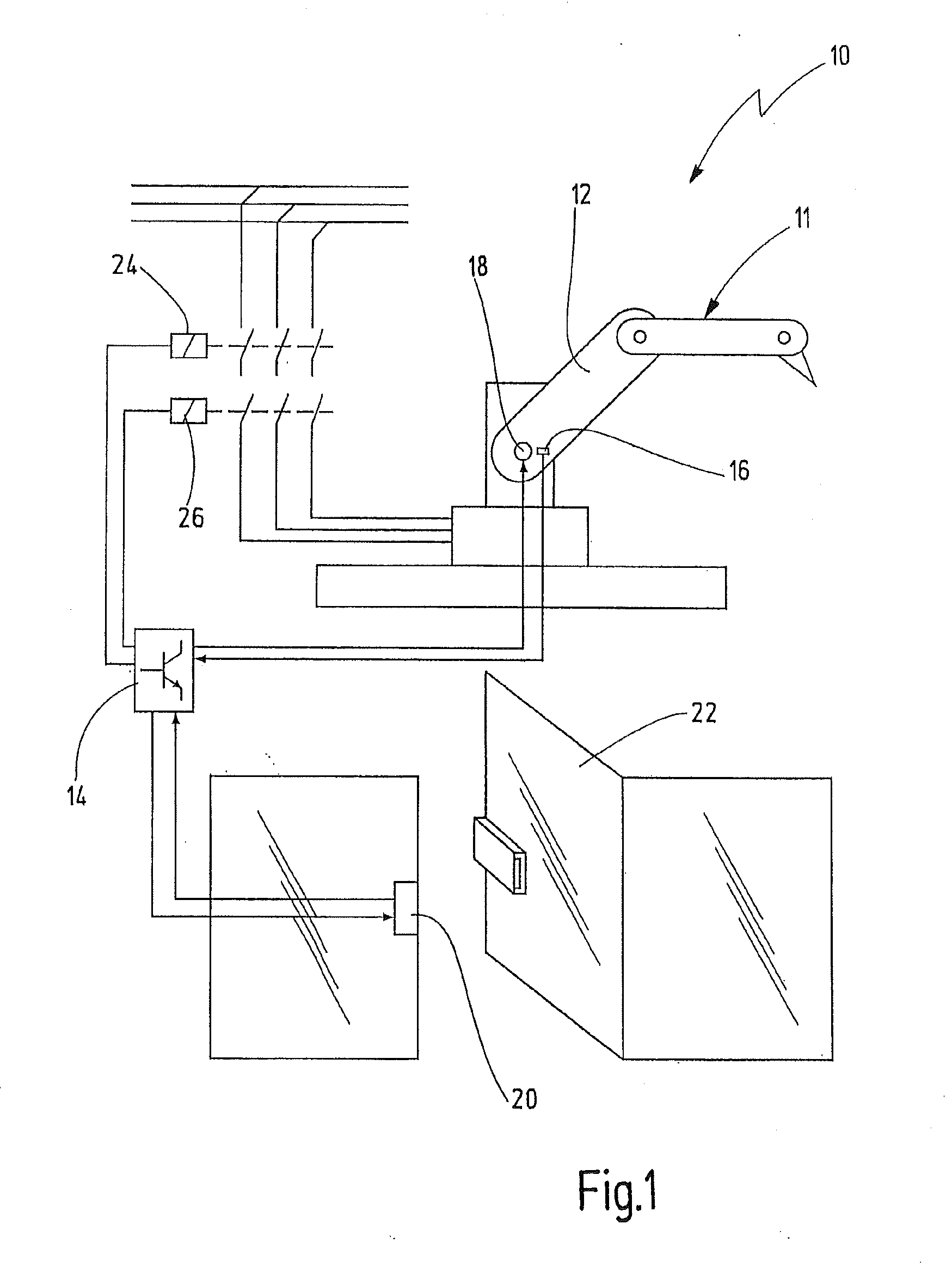
[0045]FIG. 1 shows a simplified illustration of an installation 10 which is controlled and programmed in accordance with a preferred embodiment of the present invention. By way of example, the installation 10 comprises a robot 11 having a movable robot arm 12. The movements of robot arm 12 are controlled by a programmable controller 14. Controller 14 receives signals from sensors which are configured to measure or detect physical quantities representing a real system state such as, for example, a position or a speed of the robot arm 12 at a defined instance of time. The sensor signals are transmitted to the controller 14 so that the controller 14 receives sensor data representing the respective real system state measured or detected by the sensor. By way of example, a sensor 16 is shown in FIG. 1 in proximity to a rotary drive 18. Sensor 16 is configured to detect an instantaneous movement position of drive 18. Drive 18 is configured to move the robot arm 12 in response to control s...


PUM


Abstract

An installation comprises at least one sensor for providing sensor data representing a real system state of the installation and at least one actuator for acting on the real system state. A controller for controlling the installation comprises a data memory for storing the sensor data and a program memory for storing a machine code program. A programming tool for programming the controller includes a program editor, a debugging tool and a compiler. A machine code program is executed on the controller while the debugging tool is activated, and the debugging tool determines a reverse relationship between the machine code running on the controller and at least one high level control instruction shown in the program editor. The debugging tool reads sensor data from a data memory in the controller and assigns the sensor data to the at least one high level control instruction, thereby linking the at least one high level control instruction to a real system state during the execution of the machine code program.

Description

CROSS-REFERENCES TO RELATED APPLICATIONS[0001]This application claims priority from European patent application EP 09 158 215.5 filed on Apr. 20, 2009 with the European Patent Office.BACKGROUND OF THE INVENTION[0002]The present invention relates to a method and a device of programming an industrial controller for controlling an automated installation, and more particularly to a method and a device using a debugging tool to facilitate analysis of the resulting controller program.[0003]In the world today, many technical processes run automated or at least partially automated. Examples can be found at industrial manufacturing sites and production plants, but also in daily life situations at the luggage claim of airports, ski lifts in skiing resorts, roller coasters at entertainment parks etc. Machines and other components of such an installation are operated by industrial controllers which receive and process sensor data from sensors in the installation and which produce control signal...

Claims


Application Information

Patent Timeline
IPC IPC(8): G05B19/42G06F9/45G06F9/44
CPCG05B19/05
Inventor CANTARELLI, MATTEOREUSCH, MATTHIASWALTER, HERBERTSTANKO, FLORIANNAWRATIL, TIMO
Owner PILZ (COMPANY)
Why Eureka
Try Eureka