Control device for vehicle drive unit

Inactive Publication Date: 2010-10-21
TOYOTA JIDOSHA KK
View PDF18 Cites 47 Cited by
  • Summary
  • Abstract
  • Description
  • Claims
  • Application Information

AI Technical Summary

Benefits of technology

[0048]According to the first aspect of the present invention, when the reservation of the torque regulation is received, computed from the current engine operating condition is the period required to realize the future target of torque included in the reservation information, which is the period required when the main-actuator is operated to regulate the torque of the internal combustion engine. Then, at the timing preceding the reserved realization timing by the required period, the operation of the main-actuator is started for realizing the reserved future target. Such advancing operation of the main-actuator makes it possible to realize surely the reserved future target of torque just at the reserved realization timing.
[0049]Furthermore, according to the first aspect of the present invention, the sub-actuator is operated in parallel with the operation of the main-actuator to cancel out torque change induced by the operation of the main-actuator during the period from the start of the operation of the main-actuator to the reserved realization timing. Such operation of the sub-actuator makes it possible to suppress an unnecessary torque change before the reserved realization timing. Also, because the required period is neither too short nor too long to realize the future target at the reserved realization timing, and the sub-actuator is operated within the required period, it is possible to minimize the operating period of the sub-actuator. Thus, according to the first aspect of the present invention, the realization of desired torque is achieved with the interposition of the sub-actuator held to the minimum necessary.
[0050]According to the second aspect of the present invention, when the time rate of torque change to the future target is achieved by the operation of the main-actuator alone, the torque regulation is performed only by the operation of the main-actuator. And only when it is impossible to achieve it by the operation of the main-actuator, the torque regulation with the interposition of the sub-actuator is performed. Thus, when the reservation information includes the start timing of the torque regulation and the time rate of tor

Problems solved by technology

However, there also exists a disadvantage of giving high impact on fuel consumption, an

Method used


Image

  • Control device for vehicle drive unit
  • Control device for vehicle drive unit
  • Control device for vehicle drive unit

Examples


first embodiment

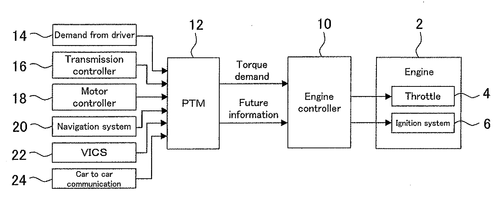
[0090]FIG. 1 is a block diagram illustrating the configuration of a control device for a vehicle drive unit as a first embodiment of the present invention. The control device of the present embodiment is configured as the control device of a vehicle drive unit having a spark-ignited internal combustion engine 2 (hereinafter referred to as an engine) as the power plant. The configuration of the control device of the present embodiment is explained referring to FIG. 1 as follows.

[0091]The control device of the present embodiment includes an engine controller 10 controlling the engine 2 directly. Two types of actuators 4, 6 concerning the torque control of the engine 2 are connected to the engine controller 10. These actuators 4, 6 are operated in response to input signals and make the engine 2 realize the torque in accordance with the operation. The present embodiment performs the torque regulation of the engine 2 by making these actuators 4, 6 collaborate. However, two actuators 4, 6...

second embodiment

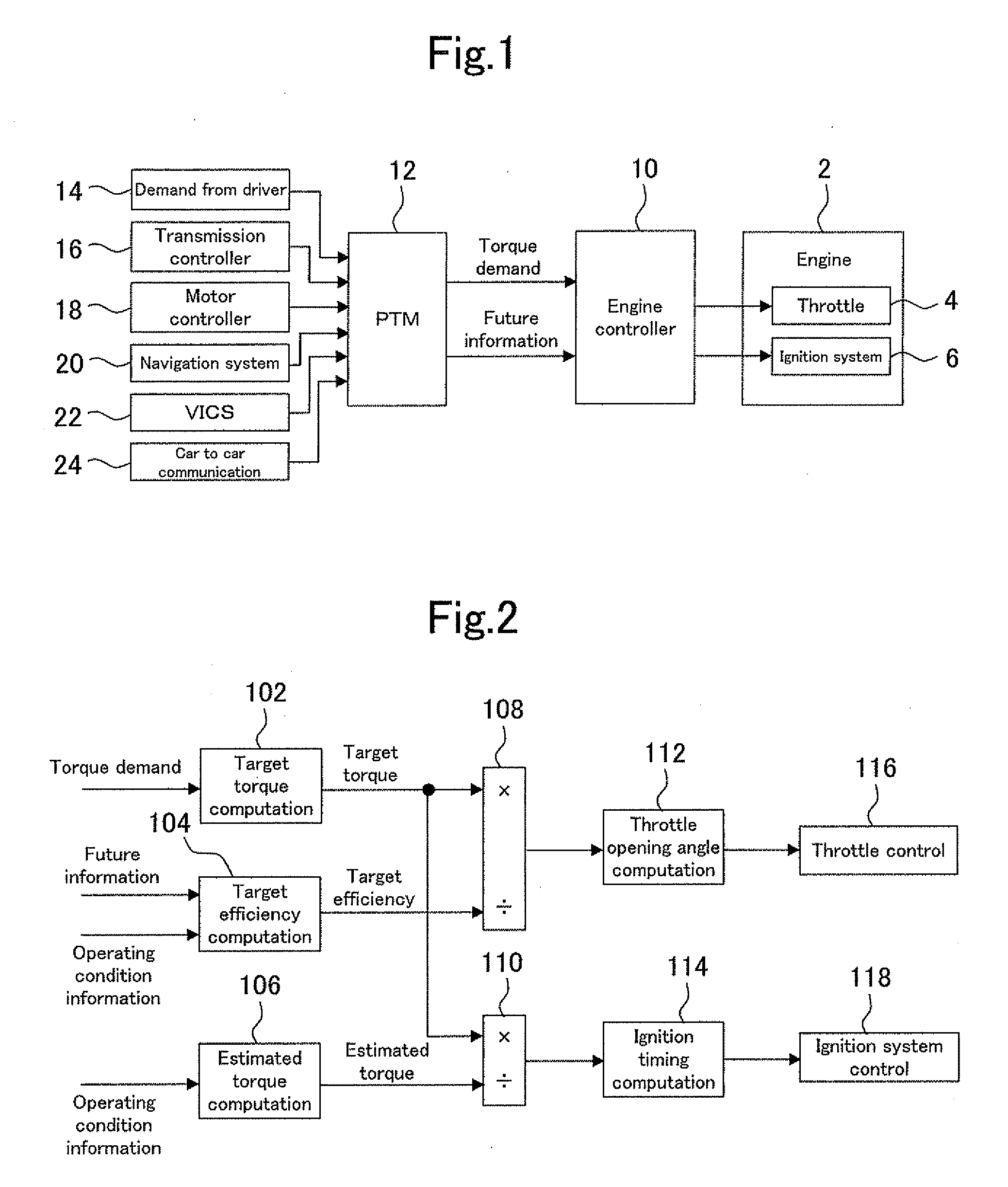
[0139]The control device according to the second embodiment of the present invention differs from the control device according to the first embodiment in the content of the future information (the reservation information) supplied from the power train manager 12 to the engine controller 10. The configuration of the control device is common to the first embodiment and the present embodiment. The overall configuration is shown in FIG. 1. The detailed configuration of the engine controller 10 is shown in FIG. 2.

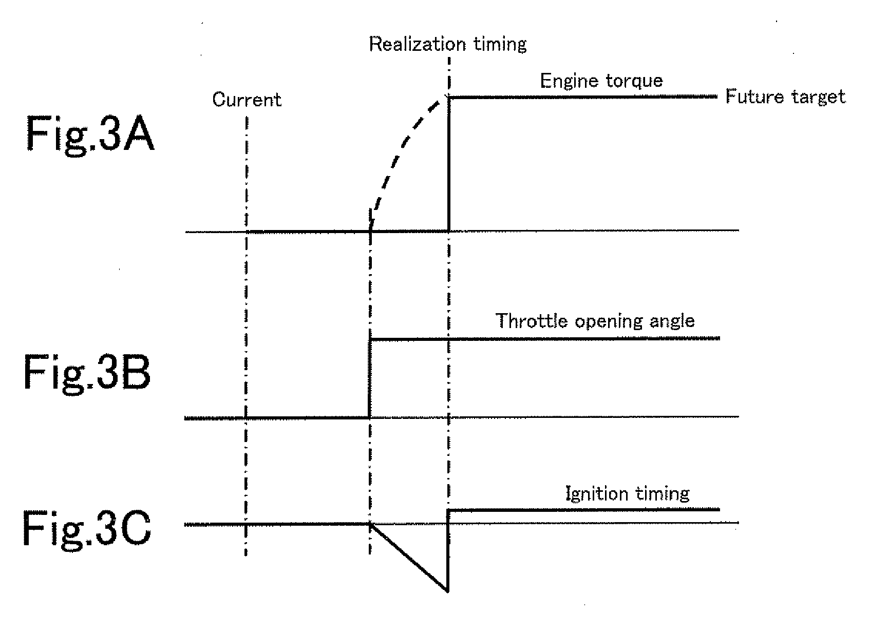
[0140]In the present embodiment, only a future target value and its realization timing are supplied to the engine controller 10 as the future information. An example of the future information is shown by the use of a time chart of FIG. 9. As shown in FIG. 9, all things that can be read out from the future information are only the future target of torque and its realization timing (Te), that is the regulation completion timing. The start timing of the torque regulation and the ti...

third embodiment

[0148]FIG. 11 is a block diagram illustrating the configuration of a control device for a vehicle drive unit as the third embodiment of the present invention. Elements that are shown in FIG. 11 and identical with those of the control device according to the first embodiment are assigned the same reference numerals as their counterparts. The control device according to the present embodiment is different from the control device according to the first embodiment only in the configuration of the engine controller 30. Other elements of the control device according to the present embodiment are identical with those of the first embodiment.

[0149]The engine controller 30 is supplied with a torque demand and future information from the power train manager 12 which is superior to it. The supply of the future information means a reservation of the torque regulation in the engine 2 made by the power train manager 12. The future information received by the engine controller 30 is treated as a r...


PUM


Abstract

This invention is intended to ensure that a control device for a vehicle drive unit is capable of realizing desired torque by making the main-actuator and sub-actuator collaborate adequately while holding the interposition of the sub-actuator as low as possible. For this end, a future target of torque that is going to be output from the engine and a realization timing of the future target are taken as reservation information for reserving engine torque regulation. Next, the required period, which is required to realize the future target when a main-actuator (a throttle) is operated to regulate the torque, is computed from a current engine operating condition. Then, the operation of the main-actuator is started at the timing preceding the realization timing by the required period for realizing the future target. In parallel with that, a sub-actuator (an ignition system) is operated to cancel out a torque change induced by the operation of the main-actuator during the period from the start timing of the operation of the main-actuator to the realization timing.

Description

FIELD OF THE INVENTION[0001]The present invention relates to a control device for a vehicle drive unit having an internal combustion engine as a power plant, in particular, a control device comprising a main-actuator and a sub-actuator which are capable of regulating torque of the internal combustion engine independently of each other.BACKGROUND ART[0002]An internal combustion engine is used as a power plant of a vehicle drive unit for an automobile. As for a spark-ignited internal combustion engine, it is equipped with a throttle and an ignition system as actuators for regulating the torque. A throttle can be used to regulate torque by controlling an intake air amount. An ignition system can be used to regulate torque by an ignition timing.[0003]There exist both advantages and disadvantages about each actuator. If a throttle and an ignition system are taken for examples, the advantage of the ignition system while comparing with the throttle is in its superior torque response to an ...

Claims


Application Information

Patent Timeline
IPC IPC(8): G06F19/00F02P5/15F02D9/02F02D41/04F02D45/00
CPCB60W2710/0616Y10T477/677F02D37/02F02D41/0085F02D41/10F02D41/307F02D2200/602F02D2200/701F02D2250/18F02D2250/22F02N11/04F02N2200/046F02P5/1504Y02T10/46F02D11/105Y02T10/40B60W50/0097
Inventor SOEJIMA, SHINICHIKAKO, JUNICHIOHTSUKA, KAORUTANAKA, HIROYUKIKAWAI, KEISUKE
Owner TOYOTA JIDOSHA KK
Why Eureka
Try Eureka