Control device for vehicle drive unit
a technology for controlling devices and drive units, applied in the direction of electric control, ignition automatic control, instruments, etc., can solve the problems of high impact on fuel consumption, and achieve the effect of preventing useless operation of sub-actuators, reducing the operating period of sub-actuators, and high respons
- Summary
- Abstract
- Description
- Claims
- Application Information
AI Technical Summary
Benefits of technology
Problems solved by technology
Method used
Image
Examples
first embodiment
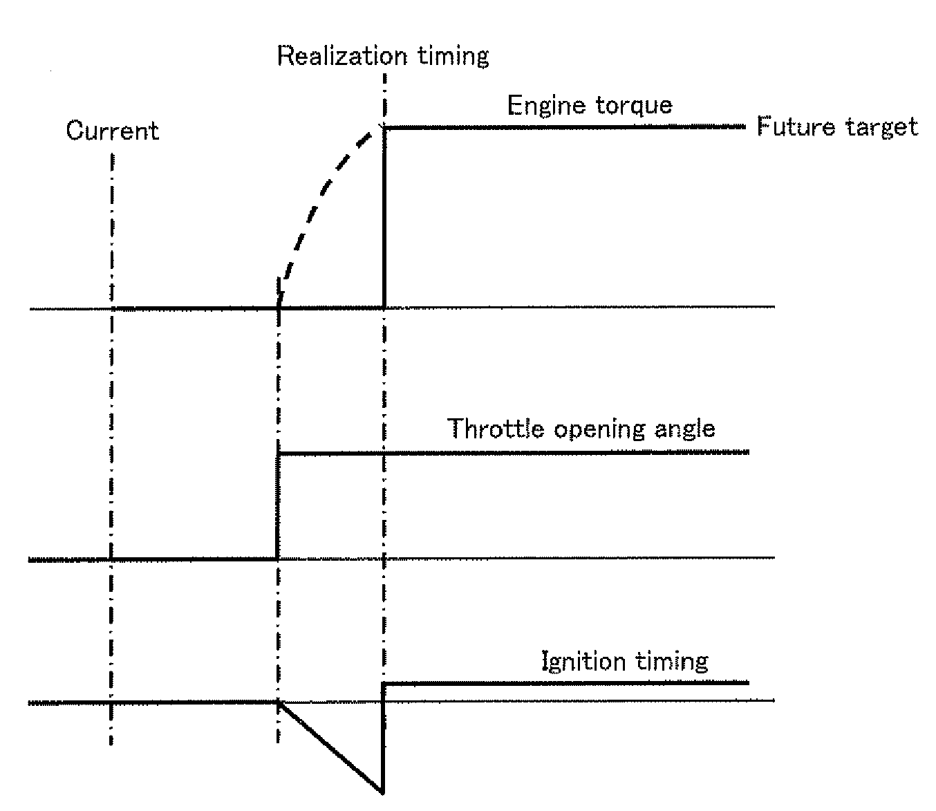
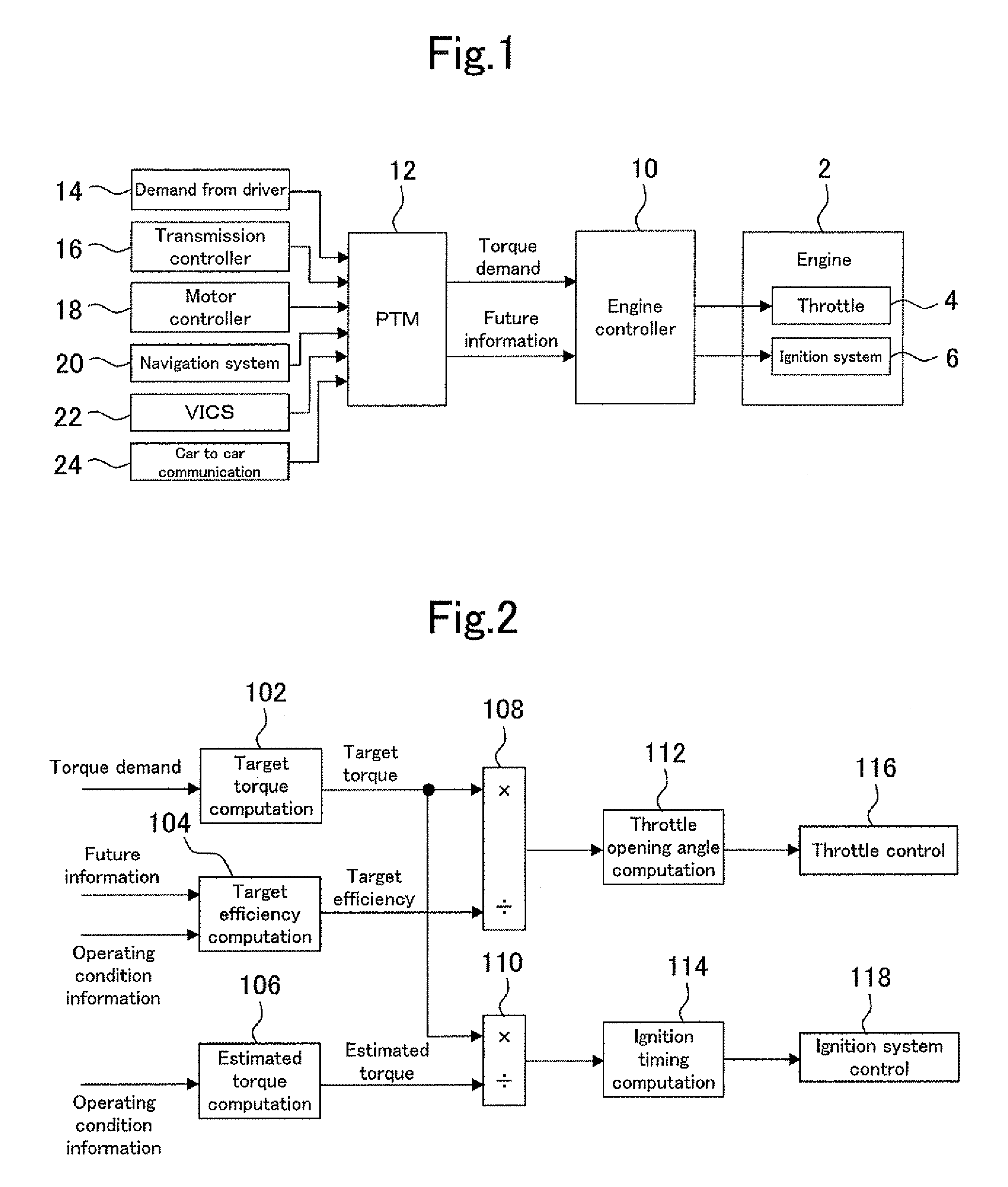
[0090]FIG. 1 is a block diagram illustrating the configuration of a control device for a vehicle drive unit as a first embodiment of the present invention. The control device of the present embodiment is configured as the control device of a vehicle drive unit having a spark-ignited internal combustion engine 2 (hereinafter referred to as an engine) as the power plant. The configuration of the control device of the present embodiment is explained referring to FIG. 1 as follows.
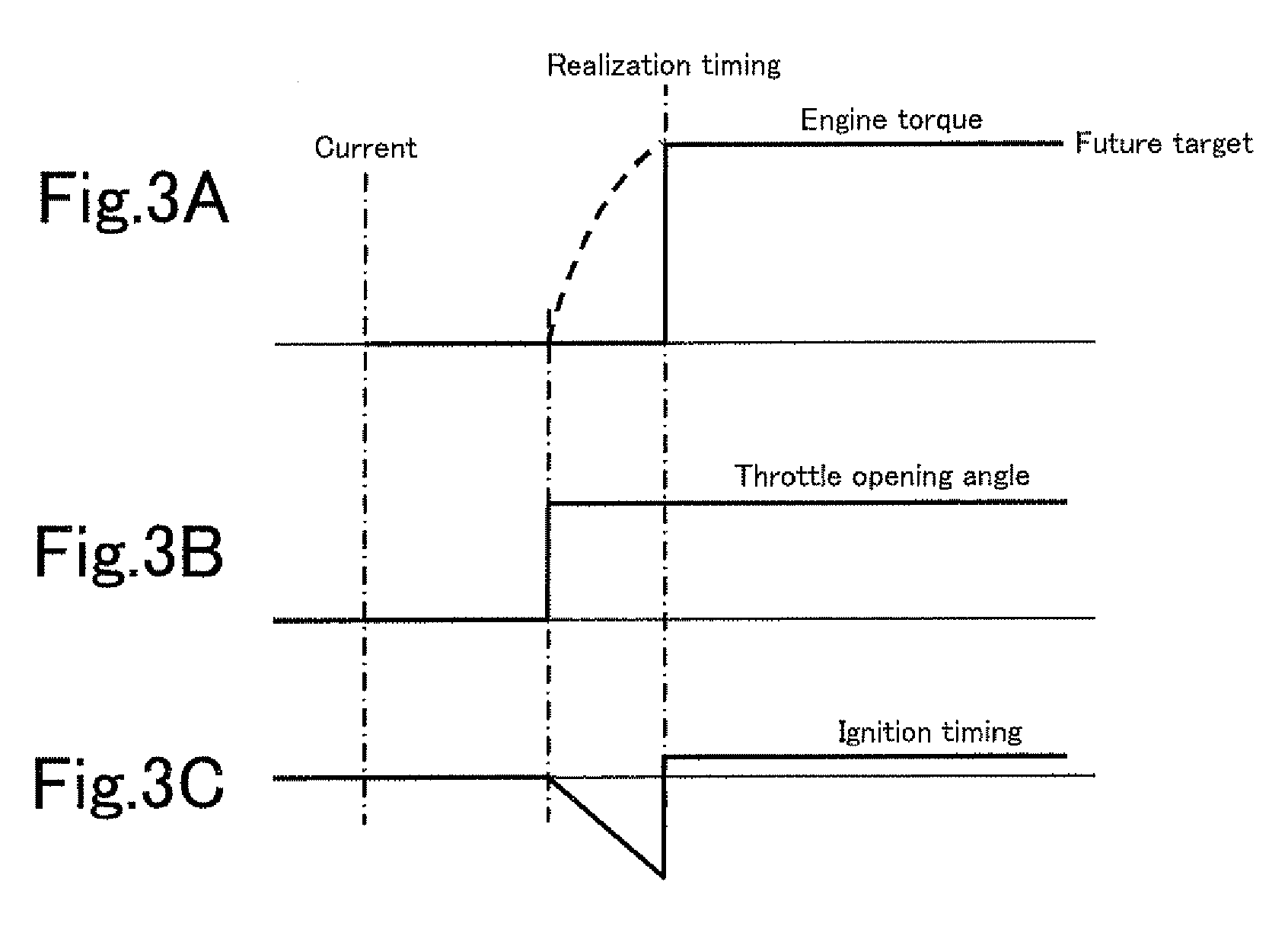
[0091]The control device of the present embodiment includes an engine controller 10 controlling the engine 2 directly. Two types of actuators 4, 6 concerning the torque control of the engine 2 are connected to the engine controller 10. These actuators 4, 6 are operated in response to input signals and make the engine 2 realize the torque in accordance with the operation. The present embodiment performs the torque regulation of the engine 2 by making these actuators 4, 6 collaborate. However, two actuators 4, 6...
second embodiment
[0139]The control device according to the second embodiment of the present invention differs from the control device according to the first embodiment in the content of the future information (the reservation information) supplied from the power train manager 12 to the engine controller 10. The configuration of the control device is common to the first embodiment and the present embodiment. The overall configuration is shown in FIG. 1. The detailed configuration of the engine controller 10 is shown in FIG. 2.
[0140]In the present embodiment, only a future target value and its realization timing are supplied to the engine controller 10 as the future information. An example of the future information is shown by the use of a time chart of FIG. 9. As shown in FIG. 9, all things that can be read out from the future information are only the future target of torque and its realization timing (Te), that is the regulation completion timing. The start timing of the torque regulation and the ti...
third embodiment
[0148]FIG. 11 is a block diagram illustrating the configuration of a control device for a vehicle drive unit as the third embodiment of the present invention. Elements that are shown in FIG. 11 and identical with those of the control device according to the first embodiment are assigned the same reference numerals as their counterparts. The control device according to the present embodiment is different from the control device according to the first embodiment only in the configuration of the engine controller 30. Other elements of the control device according to the present embodiment are identical with those of the first embodiment.
[0149]The engine controller 30 is supplied with a torque demand and future information from the power train manager 12 which is superior to it. The supply of the future information means a reservation of the torque regulation in the engine 2 made by the power train manager 12. The future information received by the engine controller 30 is treated as a r...
PUM
 Abstract
Description
Claims
Application Information
 - R&D
- Intellectual Property
- Life Sciences
- Materials
- Tech Scout
- Unparalleled Data Quality
- Higher Quality Content
- 60% Fewer Hallucinations
Browse by: Latest US Patents, China's latest patents, Technical Efficacy Thesaurus, Application Domain, Technology Topic, Popular Technical Reports.
© 2025 PatSnap. All rights reserved.Legal|Privacy policy|Modern Slavery Act Transparency Statement|Sitemap|About US| Contact US: help@patsnap.com


