Apparatus and method for clock skew adjustment in a programmable logic fabric

a programmable logic and fabric technology, applied in the direction of logic circuits using specific components, cad circuit design, pulse technique, etc., can solve the problems of affecting the delay value, limiting the time of input to output, and the signal cannot be driven from input to output. to achieve the effect of minimizing the clock period, configurable, and minimizing the clock signal

Inactive Publication Date: 2008-04-22
CHANG HYUN TAEK
View PDF2 Cites 45 Cited by
  • Summary
  • Abstract
  • Description
  • Claims
  • Application Information

AI Technical Summary

Benefits of technology

[0024]A third object of the invention is a method for finding the clock routes for a custom design implemented in a programmable logic fabric to minimize the operating period of the clock signal.
[0025]A programmable logic fabric includes a configurable logic block which has a plurality of configurable combinatorial logic elements and a plurality of configurable register elements. The configurable logic blocks are interconnected through a routing network. Ordinarily, a dedicated clock network in the logic fabric distributes a global clock signal to the clock pin of the register elements with the minimal clock skew. The present invention allows a global clock signal distributed through the dedicated clock network to be directly connected to the routing network so that the global clock signal is alternatively routed to the clock pin of a register element through the routing network, where the delay of the alternative route passing through the routing network can be used to introduce a desired amount of clock skew. In this manner, configurable clock delays for some registers may be established on a cycle-stealing clock distribution network to minimize the clock period of a synchronous circuit containing those registers.

Problems solved by technology

Variations in manufacturing process, operating voltage and temperature also affect the delay values.
In this case, the minimum period P is just a feasible solution, not necessarily an optimal solution.
In general, the more the switches in a routed path, the larger the delay in the path.
However, the signal can only be driven from input to output in a buffered switch multiplexer while it may be driven in both directions in an unbuffered switch multiplexer.
On the other hand, a clock signal routed through general purpose routing resources can not be synchronized with the clock source and may incur a large amount of clock skew due to uneven route-dependent clock delays associated with undesirable clock signal routing paths.
This approach requires significant hardware cost to implement the selectable delay lines of the units for every clock input of register elements, and it is difficult to pre-define a good set of delay values for the selectable delay lines covering wide range of the applications with different performance requirements.
The advantage of this approach is minimal hardware overhead, however, it is not applicable when all the dedicated clock lines are consumed by multiple clock signals in a custom design with multiple clock domains.
Another drawback of this approach is that it requires a special placement algorithm which takes the delay-embedded clock trees into consideration.

Method used


Image

  • Apparatus and method for clock skew adjustment in a programmable logic fabric
  • Apparatus and method for clock skew adjustment in a programmable logic fabric
  • Apparatus and method for clock skew adjustment in a programmable logic fabric

Examples


Embodiment Construction

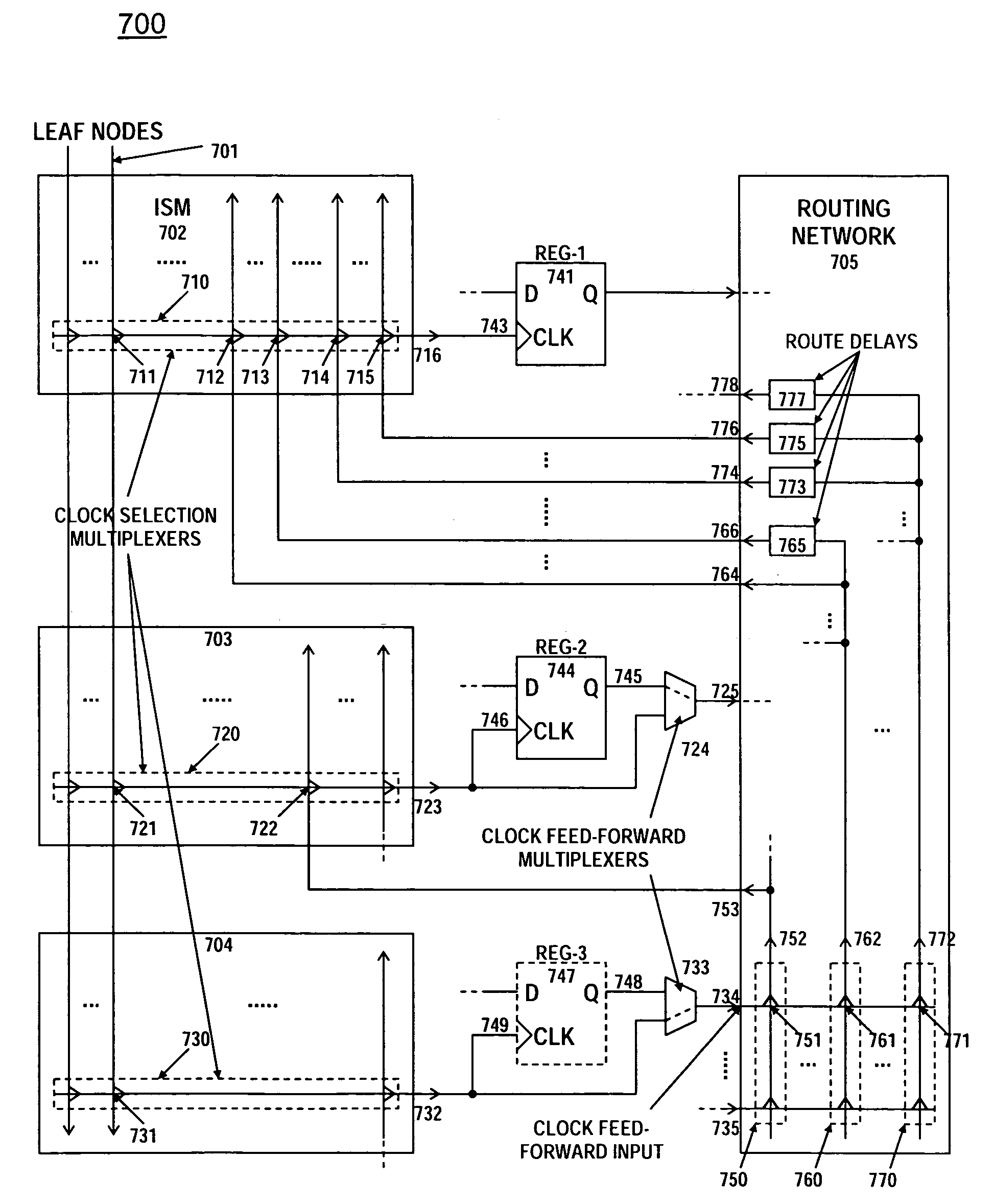
[0034]In contrast to prior art cycle-stealing configurations relying on dedicated delay line hardware with fixed delay amounts, the present invention synthesizes the delay lines with fine-grain, wide-range delay amounts by utilizing the logic and routing resources that are remaining after a custom design is completely implemented in the programmable logic fabric where the clock signals are usually routed with minimal skew wherever possible.

[0035]There are two types of delay elements in the programmable logic fabric: logic delay and interconnect delay. The logic delay is the propagation delay of a combinatorial path of a logic component such as a delay of input-to-output path 517 in LUT4530 of FIG. 5. The interconnect delay, or route delay, is a propagation delay associated with a routed path connecting one logic component to another such as the delay of a routing path from input 311 to output 313 in the routing network 310 of FIG. 3. An interconnect delay associated with a single wi...


PUM


Abstract

A programmable logic fabric includes configurable logic block (CLB) containing registers and combinatorial logic elements. An input switch matrix distributes incoming signals to CLB inputs or inputs of embedded logic elements including a register clock. A routing network allows a variety of routing paths with distinct delays to be selected to route the CLB outputs to the input switch matrices. Presented clock delay insertion architectures allow a leaf node of dedicated clock network and a register clock input can be alternatively routed through the routing network, thereby allowing for the generation of a variable amount of clock delay. Required clock delay for each register minimizing the clock period is computed by clock skew optimization program. A set of alternative clock routes is generated for each register clock where each route delay is close to the corresponding required delay while satisfying the monotone increasing conditions. Optimal clock route for each register clock can be efficiently selected from the alternative clock routes by an integer monotonic program to reduce the clock period of a custom design implemented in the fabric.

Description

FIELD OF THE INVENTION[0001]The present invention relates to the clock skew adjustment in a programmable logic fabric for use in cycle-stealing clock distribution to improve the performance of the design implemented in the logic fabric.BACKGROUND OF THE INVENTION[0002]A synchronous digital circuit comprises combinatorial logic circuitry and register elements. The register elements, such flip-flops responsive to a rising or falling edge of a periodic clock signal, store current logic states. The combinatorial logic circuitry computes the new logic states based on the current logic states and the computed logic states are stored to the registers on the next clock edge.[0003]FIG. 1 shows a generalized prior art single clock synchronous circuit 100, where a clock source 110 drives individual register clocks via a clock distribution network 120. Clock distribution network 120 is ordinarily designed to minimize clock skew, which may be defined as variations in the propagation delays from ...

Claims


Application Information

Patent Timeline
Patent Type & Authority Patents(United States)
IPC IPC(8): H01L25/00H03K19/177
CPCG06F17/5054H03K19/1774G06F30/34
Inventor CHANG, HYUN-TAEK
Owner CHANG HYUN TAEK
Why Eureka
Try Eureka