Device for supplying pressure to an actuation unit of a motor vehicle brake system and method for controlling said device

a technology of brake system and actuation unit, which is applied in the direction of braking system, rotary clutch, fluid coupling, etc., can solve the problems of service brake function and non-boosted braking in conformity

Active Publication Date: 2010-10-28
CONTINENTAL TEVES AG & CO OHG
View PDF9 Cites 17 Cited by
  • Summary
  • Abstract
  • Description
  • Claims
  • Application Information

AI Technical Summary

Benefits of technology

[0010]This object is achieved in that the control unit for controlling the motor-and-pump assembly includes a logic module and a power module, which are separated from each other. It is thereby achieved that errors of one module do not automatically have an effect on the other module and that the service brake function will not automatically fail as a consequence.
[0012]Favorable improvements of the invention provide that the control unit is used for the actuation of the motor-and-pump assembly and the brake system or for the actuation of a motor of the vehicle, that the logic module is arranged in the control unit, and that the power module is provided outside the control unit. This obviates the need for a separate control unit for the motor-and-pump assembly and allows economizing extra costs for additional components, failsafe, etc. The logic module for the actuation of the motor-and-pump assembly can be integrated almost without additional expenditure into the control unit of the brake system that is already provided. On the other hand, the power module comprises large electronic components such as relays or MOSFETs and requires a correspondingly large mounting space so that it is preferably provided at the motor-and-pump assembly or in another control unit of the vehicle. In this respect, it is likewise advantageous that a great temperature rise of the power module does not have any effect on the control unit of the motor-and-pump assembly and the brake system or on the control unit of the motor because corresponding structural measures for the dissipation of heat from the control unit would become necessary when integrating the power module into the control unit.

Problems solved by technology

It is disadvantageous in systems without a boosted mechanical fallback mode that the service brake function, i.e. boosted braking, is given only when the electric energy supply exists.
Failure of the electric energy supply or a defect in the electric control unit will cause that e.g. in a hydraulic brake-by-wire bake system, that means an electro-hydraulic brake (EHB), only non-boosted braking is possible in conformity with legal conditions (0.3 g with 500 N pedal force).

Method used


Image

  • Device for supplying pressure to an actuation unit of a motor vehicle brake system and method for controlling said device
  • Device for supplying pressure to an actuation unit of a motor vehicle brake system and method for controlling said device
  • Device for supplying pressure to an actuation unit of a motor vehicle brake system and method for controlling said device

Examples


first embodiment

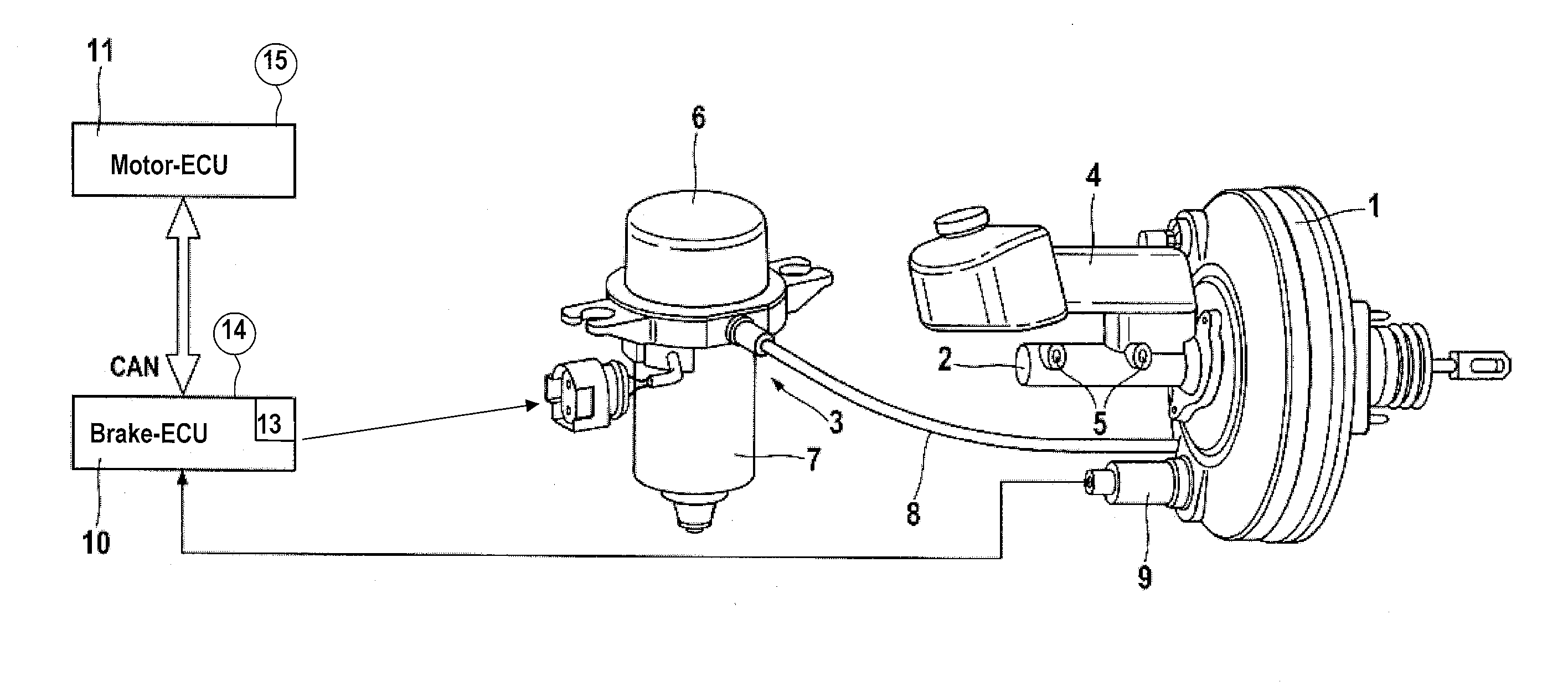
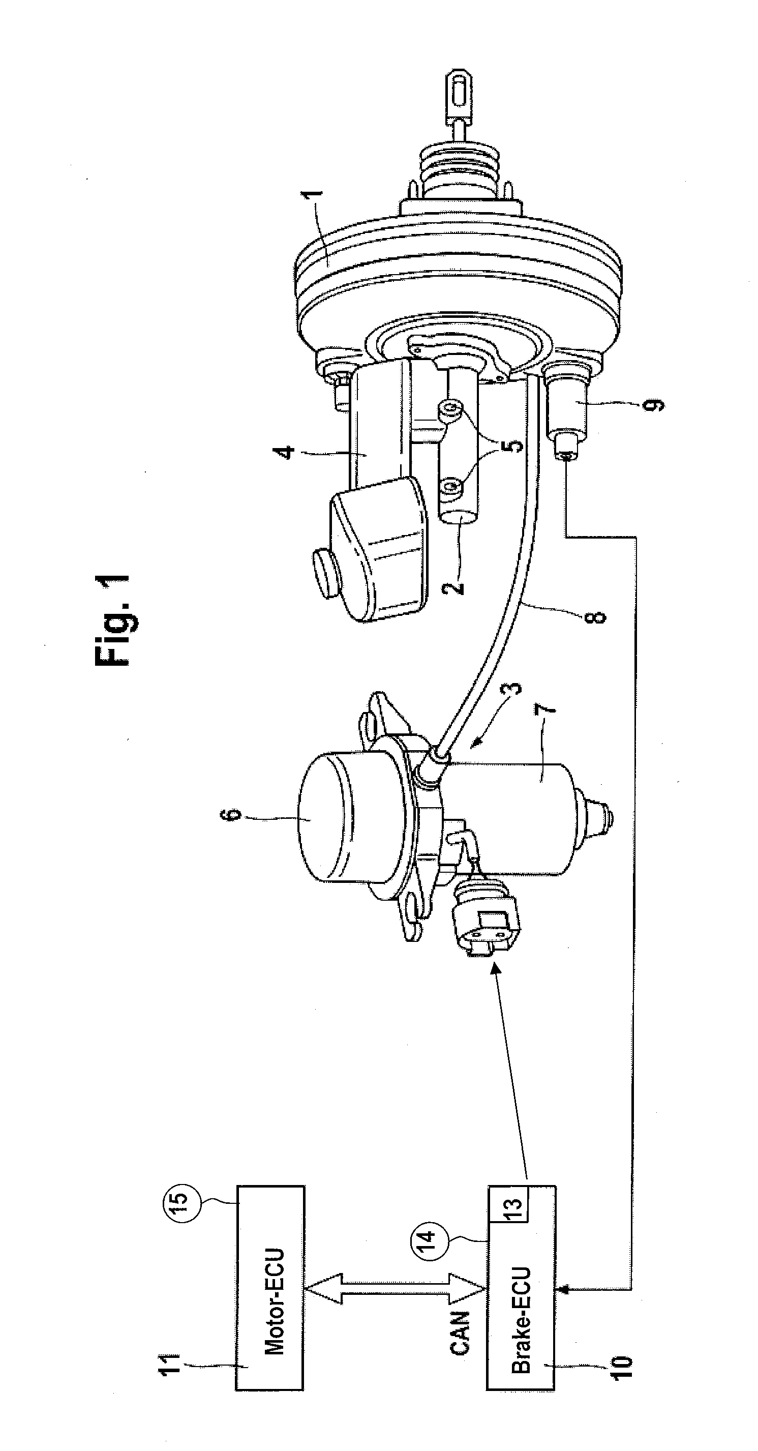
[0024]FIG. 1 shows a schematic system configuration of a device of the invention;

second embodiment

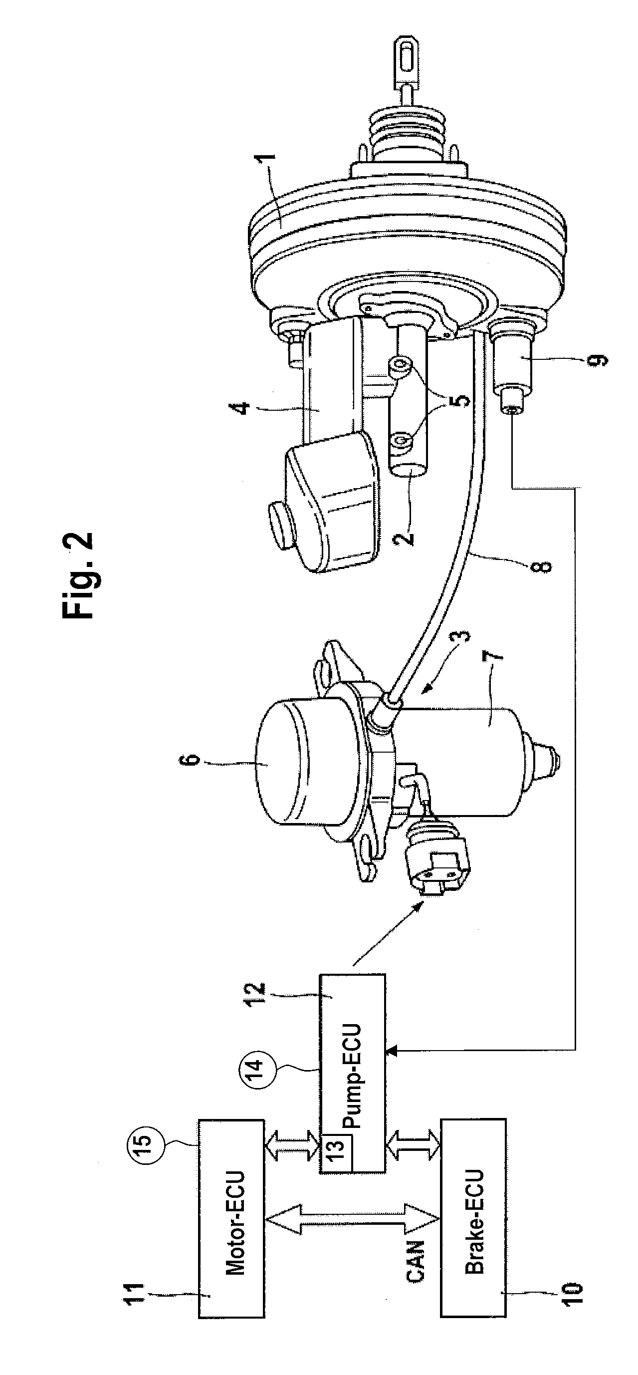
[0025]FIG. 2 shows a schematic system configuration of a device of the invention, and;

third embodiment

[0026]FIG. 3 shows a schematic system configuration of a device of the invention.

DETAILED DESCRIPTION OF THE PREFERRED EMBODIMENTS

[0027]FIG. 1 shows a schematic system configuration of a first embodiment of a device of the invention for supplying pressure to an actuating unit of a vehicle brake system of the ‘brake-by-wire’ type. It can be seen that the actuation unit comprises a pneumatic brake booster 1, and a master brake cylinder 2 arranged thereat. Vehicle brake systems of the ‘brake-by-wire’ type can be actuated in response to the driver's request by means of an electronic control unit (ECU), i.e. irrespective of the driver, but also partly by means of a brake pedal (not shown) (mechanical fallback mode).

[0028]The principal design and the function of the actuation unit are generally known so that only the features essential for the invention will be described in the following.

[0029]An inner space (not shown) of the brake booster 1 is subdivided by a movable wall into at least ...


PUM


Abstract

A device for supplying pressure to an actuation unit of a vehicle brake system, in particular to a vehicle brake system of the ‘brake-by-wire’ type, comprising a pneumatic motor-and-pump assembly with a pump and a motor driving the pump, wherein the motor-and-pump assembly is controlled by an electronic control unit depending on a pressure level or pressure difference in a pneumatic brake booster of the actuation unit, with the pressure level in a chamber or a difference in pressure between two chambers of the brake booster being detected by means of a sensor. In order to maintain the availability of the service brake function as high as possible and to obtain a maximum possible redundancy, the control unit, used to control the motor-and-pump assembly comprises a logic module and a power module, which are arranged separately of each other.

Description

[0001]This application is a Continuation Patent Application of U.S. patent application Ser. No. 11 / 659,441, filed Feb. 2, 2007, which is the U.S. national phase application of PCT International No. PCT / EP2005 / 053835, filed Aug. 4, 2005, which claims priority to German Patent Application No. DE102004038549.1, filed Aug. 6, 2004, and German Patent Application No. DE102005036615.5, filed Aug. 1, 2005.BACKGROUND OF THE INVENTION[0002]1. Technical Field[0003]The present invention relates to a device for supplying pressure to an actuation unit of a vehicle brake system, in particular to a vehicle brake system of the ‘brake-by-wire’ type, comprising a pneumatic motor-and-pump assembly with a pump and a motor driving the pump, wherein the motor-and-pump assembly is driven by an electronic control unit depending on a pressure level or pressure difference in a pneumatic brake booster of the actuation unit, with the pressure level in a chamber or a difference in pressure between two chambers o...

Claims


Application Information

Patent Timeline
Patent Type & Authority Applications(United States)
IPC IPC(8): B60T13/66B60T13/24
CPCB60K6/543B60T8/321B60T8/4077B60T8/885B60T13/52B60W20/00B60T17/02B60T2270/402B60T2270/404B60T2270/414B60W10/30B60T13/72B60T13/46B60W30/18109
Inventor RUFFER, MANFREDFACHINGER, GEORGWAHL, HOLGERALBRICHSFELD, ALBRICH VONKARL, UWE
Owner CONTINENTAL TEVES AG & CO OHG
Why Eureka
Try Eureka