Method and Arrangement for Realizing a Vacuum in a Vacuum Chamber

a vacuum chamber and vacuum technology, applied in the direction of gas/liquid distribution and storage, pumping plants, nanotechnology, etc., can solve the problems of disfavored arrangement, achieve the effect of reducing the influence of external vibration, reducing the piping, and reducing the pumpdown tim

Inactive Publication Date: 2010-10-28
ASML NETHERLANDS BV
View PDF11 Cites 6 Cited by
  • Summary
  • Abstract
  • Description
  • Claims
  • Application Information

AI Technical Summary

Benefits of technology

[0007]By combined use of the same pumping system by the vacuum chambers it is not necessary to equip each vacuum chamber with separate equipment for establishing the vacuum. As a result, the costs of the total pumping system may be considerably reduced. Additionally, the shared pumping system occupies less fab floor space than a plurality of pumping systems would have occupied, which in itself provides its own economic and functional advantage.
[0017]In some embodiments, at least one vacuum chamber comprises one or more light emitting diodes emitting radiation in the ultraviolet spectrum. Alternatively, a vacuum chamber is arranged with dedicated wall portions for allowing the coupling of ultraviolet radiation into the chamber. The use of UV-radiation stimulate outgassing at predetermined locations in the vacuum chamber. The increased outgassing may allow for a more effective pumpdown and a lower pressure value within the vacuum chamber.

Problems solved by technology

This problem typically results in a compromise, by using a small opening in the EM shield in combination with accepting a relatively long pump down time of the charged particle system.
Such arrangements have been disfavored due to the high cost of cryogenic systems, and due to the need to retain a conventional vacuum pumping system because the cryogenic pump system operates from a predefined minimum level of vacuum.

Method used


Image

  • Method and Arrangement for Realizing a Vacuum in a Vacuum Chamber
  • Method and Arrangement for Realizing a Vacuum in a Vacuum Chamber
  • Method and Arrangement for Realizing a Vacuum in a Vacuum Chamber

Examples


Embodiment Construction

[0031]The following is a description of various embodiments of the invention, given by way of example only and with reference to the drawings.

[0032]Throughout the description the expression “vacuum” is referring to a state where the pressure is lower than 10−3 mBar.

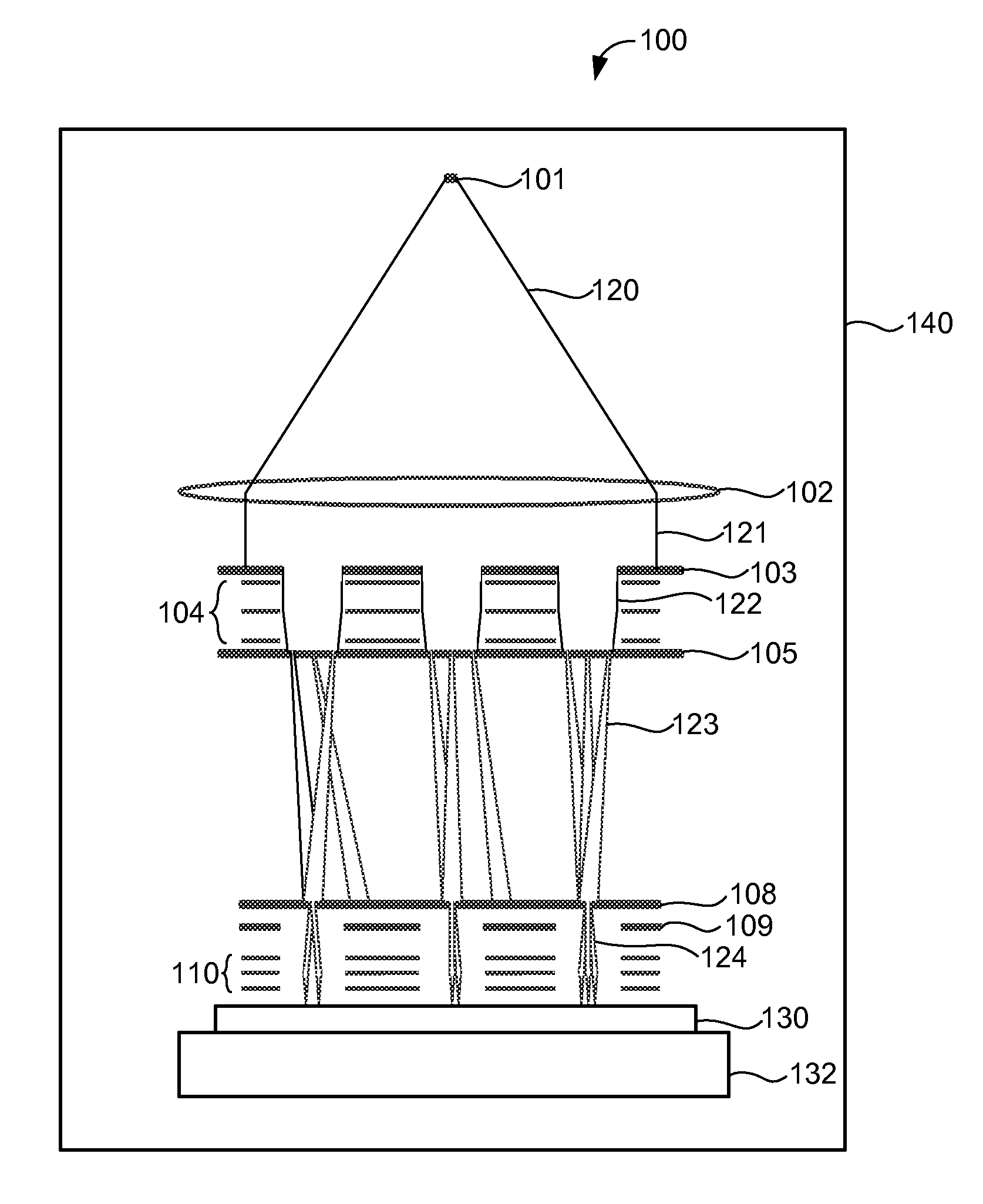
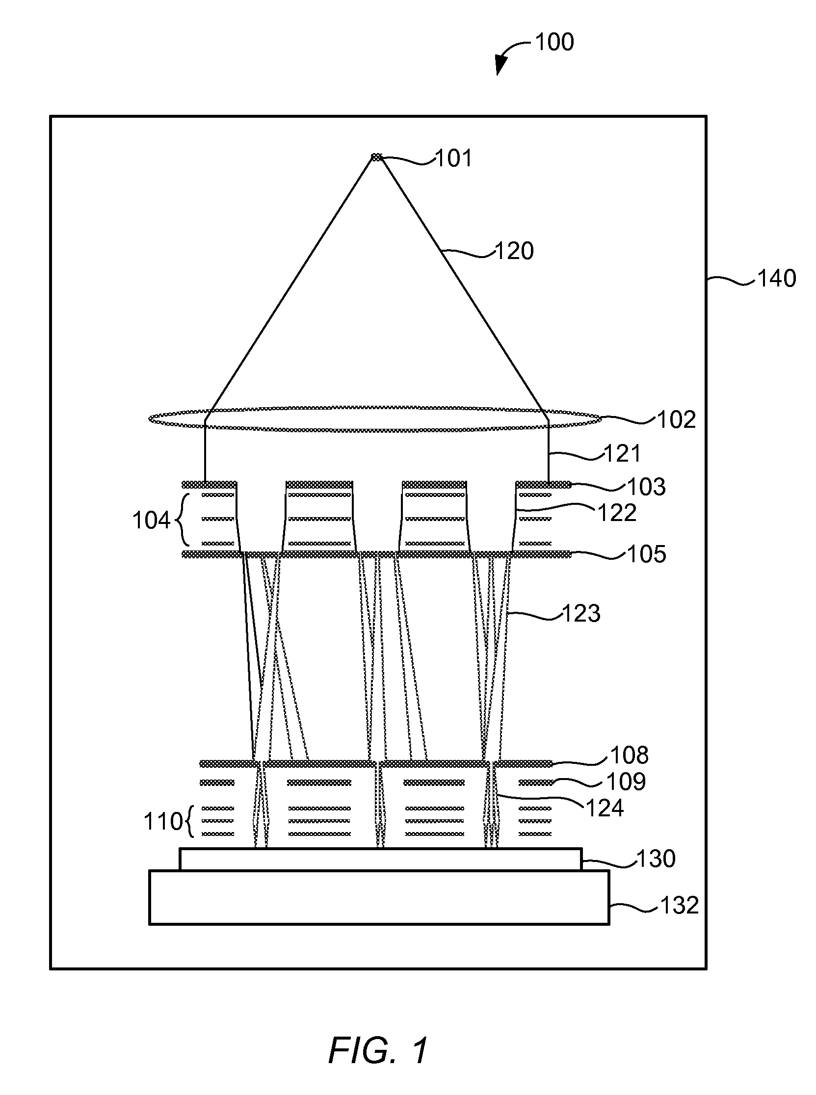
[0033]FIG. 1 shows a simplified schematic drawing of an embodiment of a charged particle lithography apparatus 100. Such lithography apparatus are described for example in U.S. Pat. Nos. 6,897,458 and 6,958,804 and 7,019,908 and 7,084,414 and 7,129,502, U.S. patent application publication no. 2007 / 0064213, and co-pending U.S. patent applications Ser. Nos. 61 / 031,573 and 61 / 031,594 and 61 / 045,243 and 61 / 055,839 and 61 / 058,596 and 61 / 101,682, which are all assigned to the owner of the present invention and are all hereby incorporated by reference in their entirety. In the embodiment shown in FIG. 1, the lithography apparatus comprises an electron source 101 for producing an expanding electron beam 120. The expanding electro...


PUM


Abstract

The invention relates to a method of realizing a vacuum in a vacuum chamber. The vacuum chamber is connected to a pumping system shared by a plurality of vacuum chambers. The method includes separately pumping down each vacuum chamber. The invention further relates to n arrangement of a plurality of vacuum chambers connected to a pumping system. In this arrangement, the pumping system is arranged for pumping down each vacuum chamber separately.

Description

CROSS REFERENCE TO RELATED APPLICATIONS[0001]This application claims priority to U.S. provisional application No. 61 / 154,415 filed on Feb. 22, 2009, U.S. provisional application No. 61 / 289,407 filed on Dec. 23, 2009, and U.S. provisional application No. 61 / 306,333 filed on Feb. 19, 2010. All three applications are hereby incorporated by reference in their entirety.BACKGROUND OF THE INVENTION[0002]1. Field of the Invention[0003]The present invention relates to a vacuum chamber arrangement, a vacuum chamber comprising an outlet for connection to a pumping system, and a method of realizing a vacuum in a vacuum chamber.[0004]2. Description of the Related Art[0005]In the semiconductor industry, an ever increasing desire to manufacture smaller structures with high accuracy and reliability makes great demands on wafer processing technology. In particular, it is important to maximize wafer throughput of wafer processing equipment while maintaining the lowest possible capital costs and opera...

Claims


Application Information

Patent Timeline
Patent Type & Authority Applications(United States)
IPC IPC(8): F17D1/16F04B41/06
CPCB82Y10/00B82Y40/00H01J37/18Y10S417/901H01J2237/1825F17D1/00H01J37/3174Y10T137/0396Y10T137/86083Y10T137/86131H01J37/22H01J37/3175H01L21/00
Inventor BALTUSSEN, SANDER
Owner ASML NETHERLANDS BV
Why Eureka
Try Eureka