

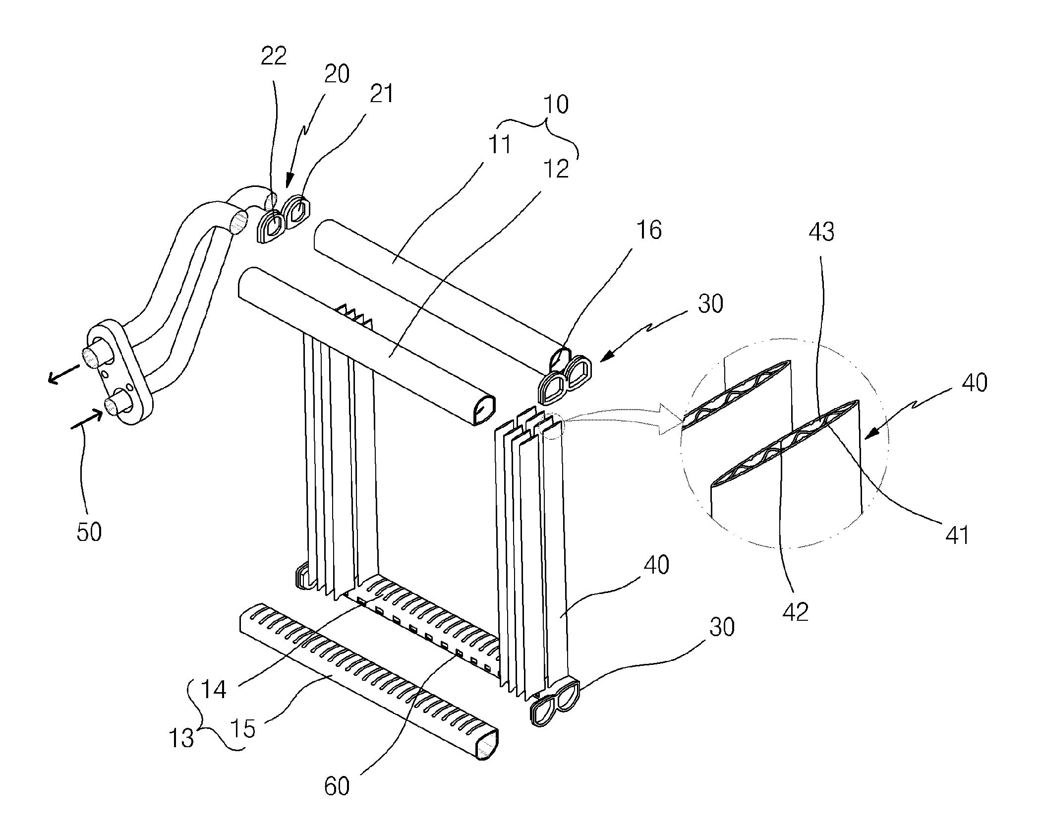
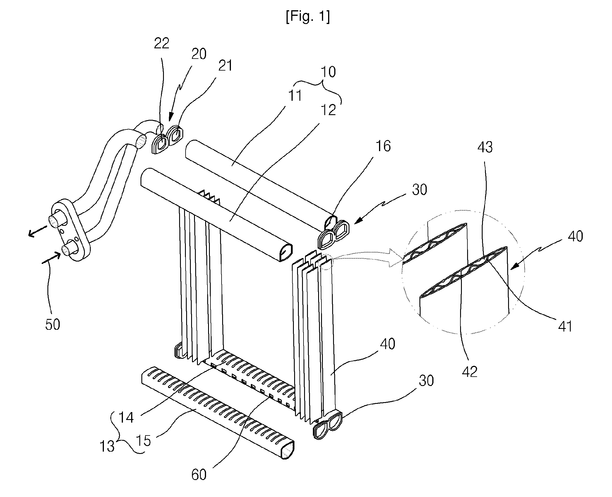
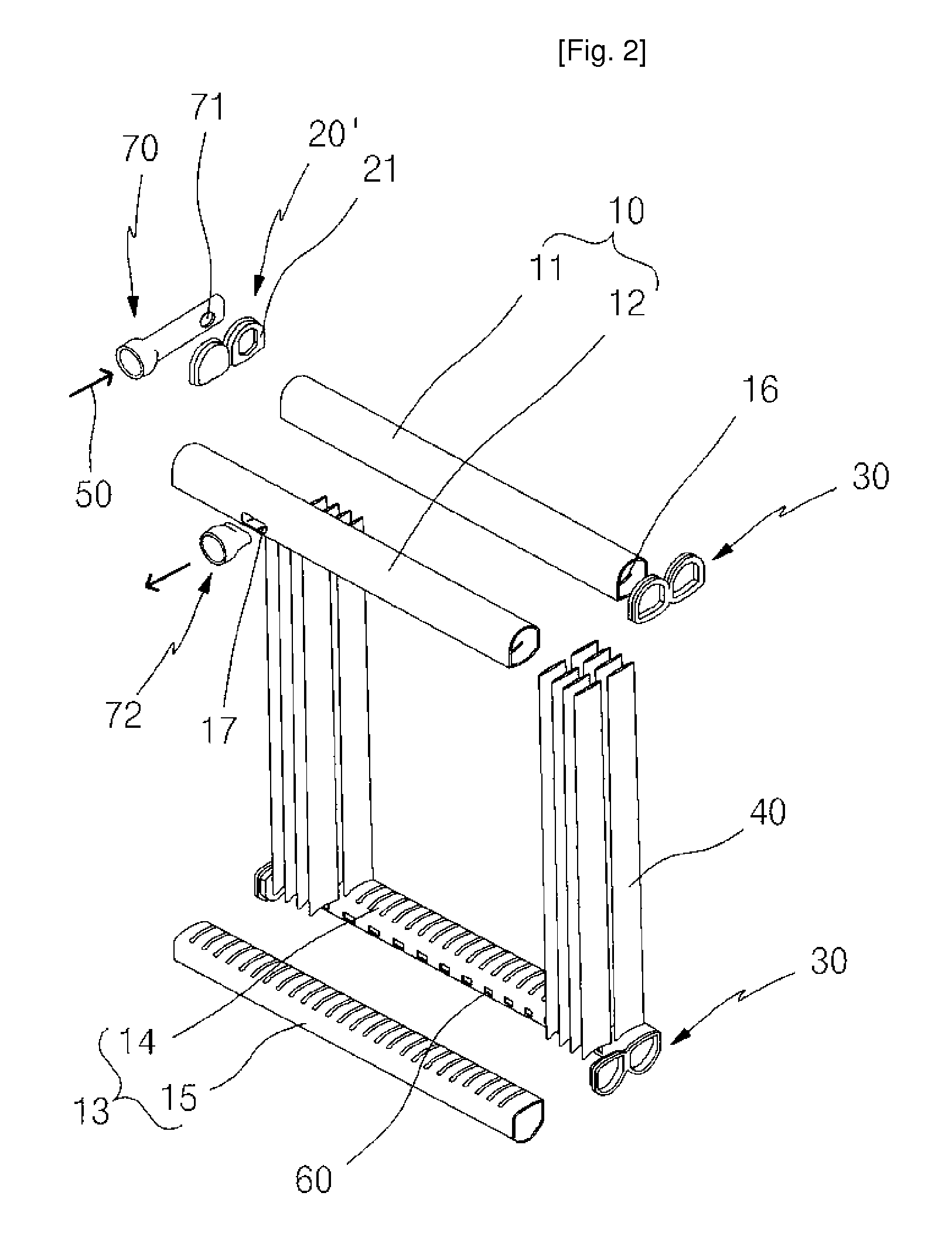
Automotive heat exchanger to the unification of header and tank and fabricating method thereof
a heat exchanger and header technology, applied in the field of automobile heat exchangers, can solve the problems of low heat exchange efficiency, easy leakage of heat exchange medium, and loss of heat radiation in both heat exchangers technology and performance, and achieve the effect of improving the ratio of radiant heat and increasing the pressure capacity of the heat exchanger
- Summary
- Abstract
- Description
- Claims
- Application Information
AI Technical Summary
Benefits of technology
Problems solved by technology
Method used
Image

Examples
Embodiment Construction
[0059]Detailed illustrative embodiments of the present invention are disclosed herein. This invention may, however, be embodied in many alternate forms and should not be construed as limited to only the embodiments of the present invention set forth herein. Accordingly, while embodiments of the present invention are capable of various modifications and alternative forms, embodiments of the present invention are shown by way of example in the drawings and will herein be described in detail.
[0060]It will be understood that when a direction of an apparatus or an element is referred to as, for example, “front”, “back”, “up”, “down”, “top”, “bottom”, “left”, “right” and “lateral”, these terms are used to simply and clearly describe the present invention and are not intended to simply mean that the apparatus or element should have a specific direction.
[0061]It will be also understood that, although the terms, such as “first”, “second”, “third” and “fourth”, these terms are used to clearly...
PUM
| Property | Measurement | Unit |
|---|---|---|
| diameter | aaaaa | aaaaa |
| diameter | aaaaa | aaaaa |
| distance | aaaaa | aaaaa |
Abstract
Description
Claims
Application Information