Exhaust muffler

a technology of exhaust muffler and exhaust pipe, which is applied in the direction of machines/engines, gas passages, gas chambers, etc., can solve the problems of unwanted oscillation of certain muffler components, unrestricted flow between the muffler pipe and the tank or sound chamber, and unwanted sound almost as bad, so as to maximize performance characteristics, reduce noise, and ensure the effect of tuning

Active Publication Date: 2010-10-28
TMG PERFORMANCE PRODS
View PDF41 Cites 35 Cited by
  • Summary
  • Abstract
  • Description
  • Claims
  • Application Information

AI Technical Summary

Benefits of technology

[0028]In accordance with the present invention, provided is a muffler which can be readily tuned to produce a desired sound in a subcompact and lightweight design allowing use in virtually all types of vehicles. More particularly, provided is a muffler that maximizes performance characteristics in a lightweight and efficient design even though it is for use with large and powerful engines.
[0029]More particularly, provided is a muffler for reducing sounds from an exhaust flow traveling through an exhaust pipe of a vehicle wherein the flow is caused by gases exhausted from one or more exhaust valves of an internal combustion engine in sound or fluid pulses relating to the flow from these one or more valves. The muffler includes an elongated fluid passage extending between a muffler inlet and a muffler outlet and the muffler inlet and muffler outlet being connectable with the exhaust pipe of the vehicle whereby the elongated fluid passage forms a portion of the exhaust pipe and has a cross-sectional area similar to the adjacent exhaust pipe. As a result, the exhaust flow travels through the elongated fluid passage without restriction. The muffler further includes a closed sound chamber surrounding the passage and this sound chamber can be formed by a side wall extending about the fluid passage and extending between two end plates. At least one tubular connector in the fluid passage extends between the end plates and provide fluid communication between the passage and the closed sound chamber. The connector has a tubular body with a first end joined to an opening in the passage and a second end opening into the closed sound chamber.
[0030]However, it has been found that while this arrangement can be effective in reducing exhaust sound, this arrangement can produce unwanted oscillation in certain muffler components wherein another aspect of the invention of this application further includes a tubular connector with a perforated resistance plate to restrict the fluid flow between the passage and the sound chamber thereby reducing the severity of the sound or fluid pulses entering and exiting the sound chamber. This resistant plate includes perforations forming an open portion of the plate, the open portion is less than 60 percent. More particularly, it has been found that unrestricted flow between the muffler pipe and the tank or sound chamber can be undesirable. This is especially true when trying to minimize the weight of the muffler. Lightening the muffler can include the use of lightweight materials when and where they can be used. One way to reduce weight is by reducing material thicknesses. Thus, thinner materials have been investigated which can drastically reduce the weight of a muffler. However, these thinner materials must still function similar to the thicker materials that they replace or they cannot be used. It was found that the material thickness of the outer walls of the muffler could only be reduced so much before they began to vibrate as the fluid pulses entered and exited the sound chamber. This vibration causes an unwanted sound that is almost as bad as the objectionable sound produced by the exhaust. While internal ribbing or other structural reinforcing members were considered, this adds weight and adds to the cost of the muffler. Thus, it was first believed that the weight reduction would not be as significant as first desired. But, the use of a restriction plate has been found to eliminate or reduce this vibration.

Problems solved by technology

However, it has been found that while this arrangement can be effective in reducing exhaust sound, this arrangement can produce unwanted oscillation in certain muffler components wherein another aspect of the invention of this application further includes a tubular connector with a perforated resistance plate to restrict the fluid flow between the passage and the sound chamber thereby reducing the severity of the sound or fluid pulses entering and exiting the sound chamber.
More particularly, it has been found that unrestricted flow between the muffler pipe and the tank or sound chamber can be undesirable.
However, these thinner materials must still function similar to the thicker materials that they replace or they cannot be used.
This vibration causes an unwanted sound that is almost as bad as the objectionable sound produced by the exhaust.
While internal ribbing or other structural reinforcing members were considered, this adds weight and adds to the cost of the muffler.

Method used


Image

  • Exhaust muffler
  • Exhaust muffler
  • Exhaust muffler

Examples


Embodiment Construction

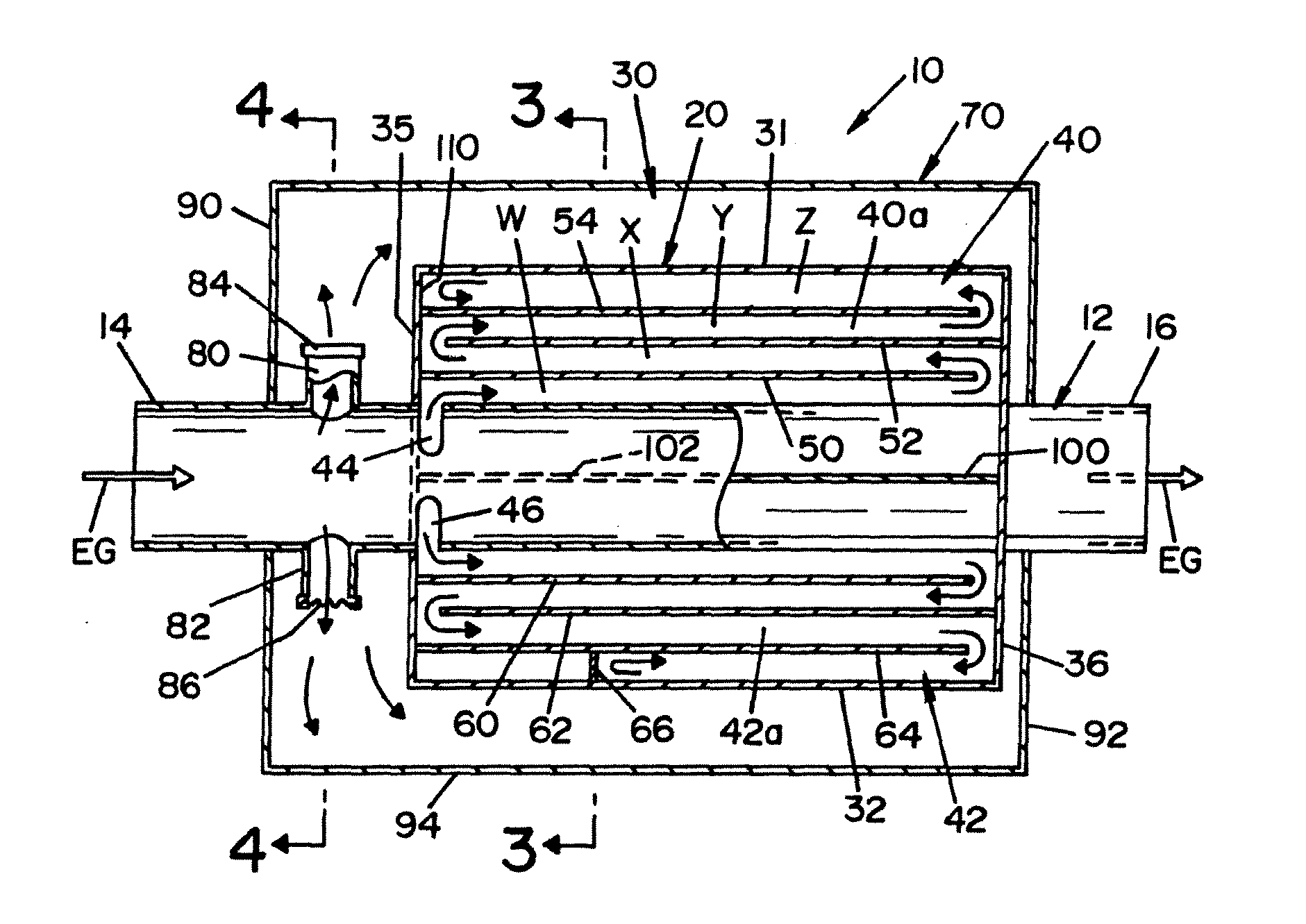
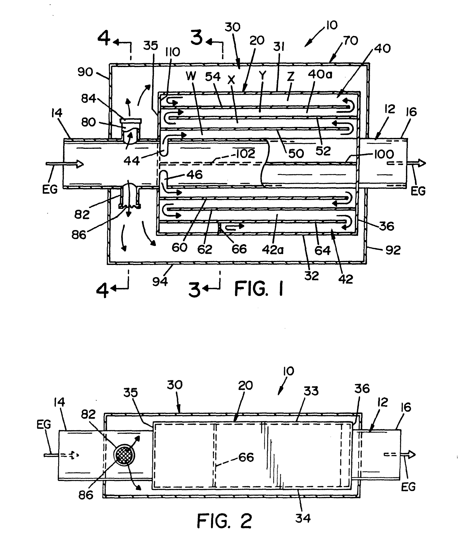
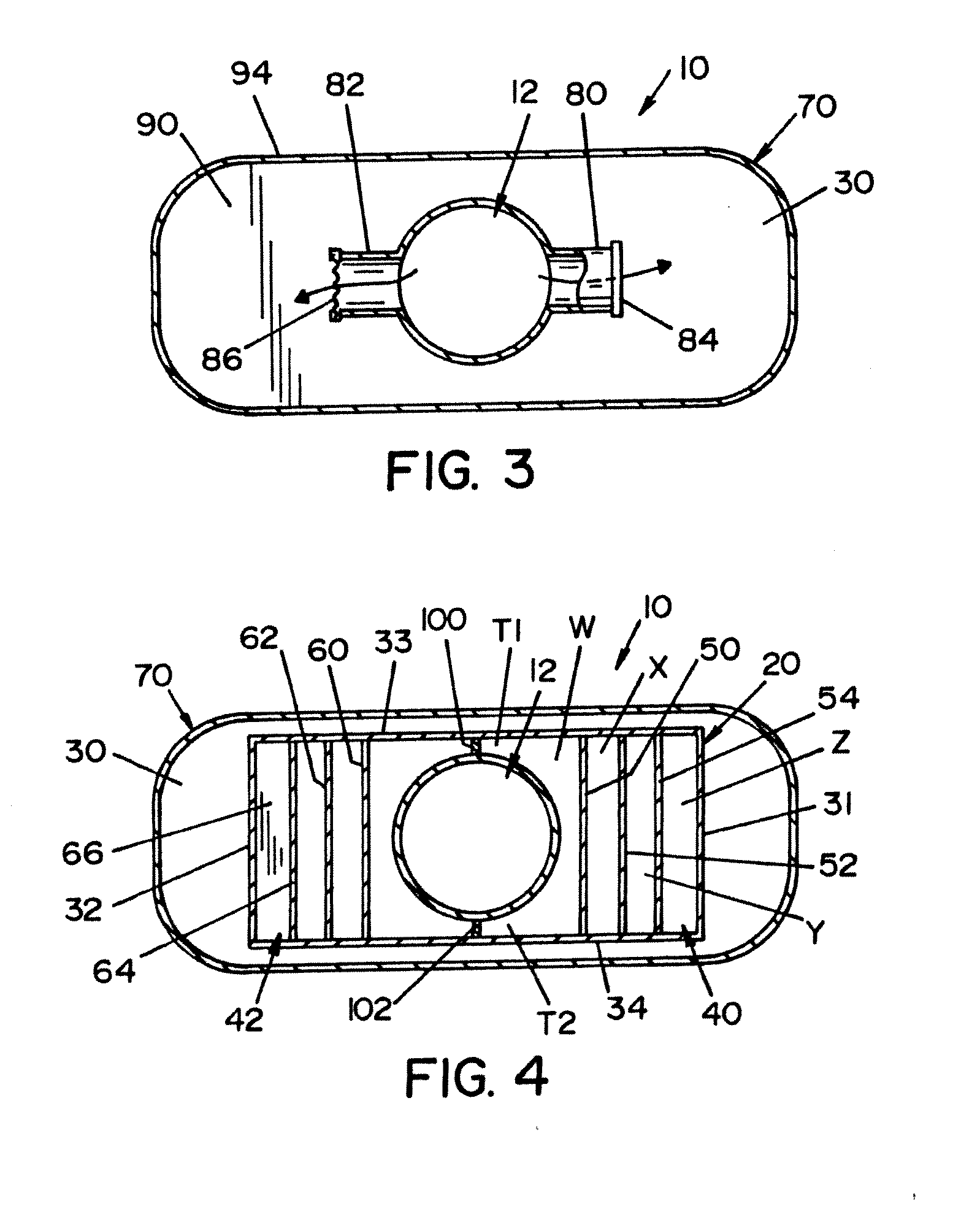
[0063]Referring now to the drawings wherein the showings are for the purpose of illustrating preferred and alternative embodiments of the invention only and not for the purpose of limiting same, there is shown in FIGS. 1-4 a muffler 10 illustrating at least one embodiment of the present invention.

[0064]Muffler 10 has an inner, axially extending through pipe or passage 12 which can be tubular, as is shown, and includes an inlet 14 and an outlet 16 wherein the exhaust of an internal combustion engine flows through muffler 10 from inlet 14 to outlet 16. Muffler 10 further includes an inner sound vessel 20 and an outer sound chamber 30. The arrows in FIG. 1, and in other Figures in this specification, generally show the flow of exhaust gases but, are illustrated in nature only in that they are intended to generally show the gas flow and / or sound or fluid pulse flow through the sound chambers at a given time and they do not show all flow patterns within muffler 10. It should be noted tha...


PUM


Abstract

A muffler for reducing the sounds of combustion gases exhausted from an internal combustion engine including an elongated fluid passage extending between an inlet and an outlet such that the outlet is in fluid communication with the inlet. Further, the inlet being connectable with the gases exhausted from the engine and the outlet being connectable with the atmosphere. The muffler further including an outer tank surrounding the passage and a tubular connector having a first end in fluid connection with the passage and a second end in fluid connection with the tank such that the connector produces a fluid connection between the passage and the tank. The connectors having a perforated resistance plate to restrict the fluid flow between said passage and said sound chamber thereby reducing the severity of the sound or fluid pulses entering and exiting said sound chamber, perforations in said perforated plate forming an open portion of said plate and said open portion being less than 60 percent.

Description

[0001]This invention relates generally to mufflers for exhaust systems of the sound modifying type used with internal combustion engines to attenuate engine noise and more particularly to mufflers conventionally referred to as side branch and / or tank muffler systems. This application claims priority in Provisional Patent Application Ser. No. 60 / 958,885 that was filed on Jul. 10, 2007 which is incorporated by reference herein and is a Continuation in Part application of U.S. non-provisional patent application Ser. No. 12 / 217,857 filed on Jul. 9, 2008 which is also incorporated by reference herein.[0002]The invention is particularly applicable to and will be described with specific reference to a side branch and / or tank style muffler for use in both cars and trucks. Further, many of these muffler designs are well suited for high-performance vehicles including high-performance cars and trucks. However, as will be appreciated by those skilled in the art that the inventive concepts discl...

Claims


Application Information

Patent Timeline
Patent Type & Authority Applications(United States)
IPC IPC(8): F01N1/08
CPCF01N1/02F01N2490/155F01N2470/14F01N1/023
Inventor HUFF, RONALD G.SKOWRONSKI, KEITHBOCKWICH, MARK
Owner TMG PERFORMANCE PRODS
Why Eureka
Try Eureka