
Microscopic bubble generating apparatus

Active Publication Date: 2010-10-28
ANLET CO LTD
View PDF8 Cites 4 Cited by
  • Summary
  • Abstract
  • Description
  • Claims
  • Application Information

AI Technical Summary

Benefits of technology

[0007]Therefore, an object of the present invention is to provide a microscopic bubble generating apparatus which can increase a dissolved oxygen level by blowing microscopic bubbles into water stored in the septic tank or the like, thereby improving the water quality.
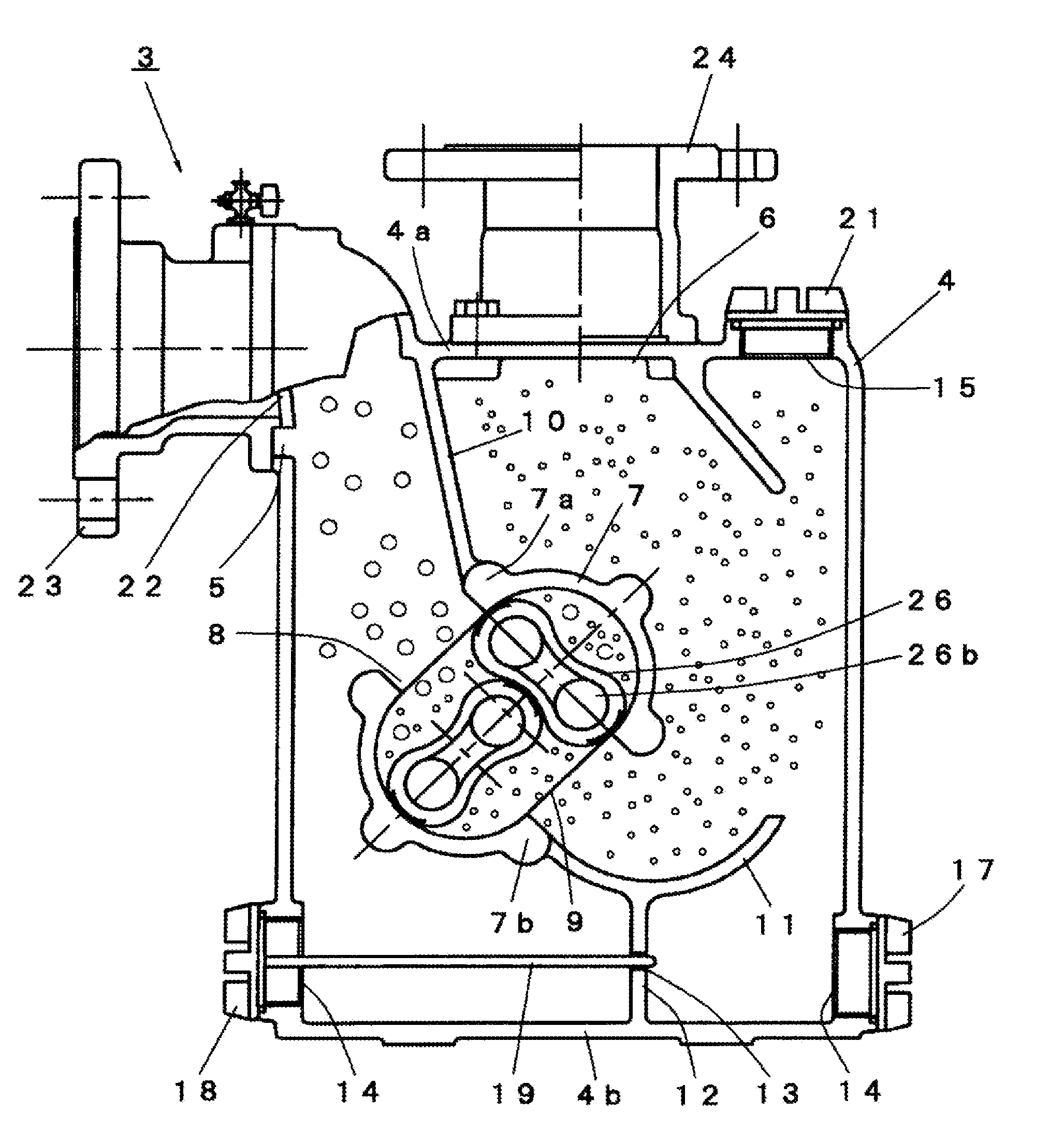
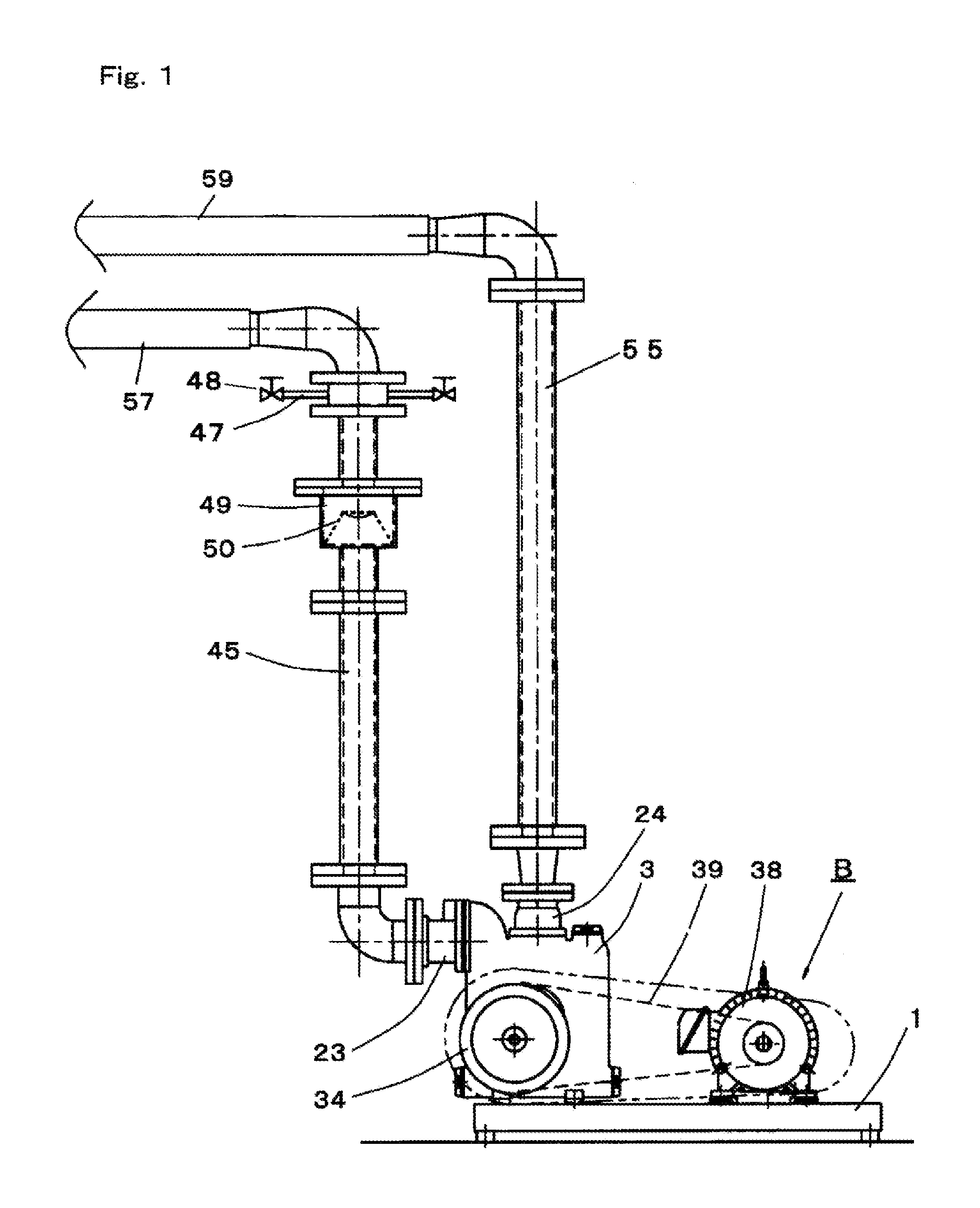
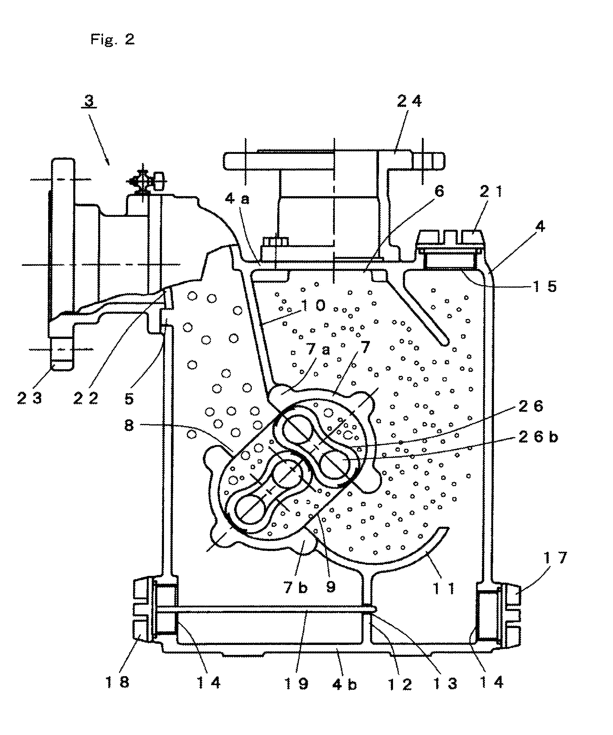
[0009]In the above-described apparatus, the Roots-type pump is operated so that the water mixed with the air sucked through the air inlet by an ejector action is caused to collide with the collision member, whereby a number of bubbles are generated. And the bubbles are refined into microscopic bubbles by the compressing action of the Roots-type pump. The water containing the microscopic bubbles is discharged from the discharge pipe into the water in the septic tank or the river. A dissolved oxygen level can be increased since the microscopic bubbles remain in the water for a long period of time. Consequently, the water quality can be improved.
[0011]The discharge pipe has a distal end provided with a nozzle with a check valve. The provision of the nozzle with the check valve can resolve an air pocket in which a part of the bubbles remain stagnant in the discharge pipe, and generation of microscopic bubbles can be enhanced. Furthermore, the nozzle with the check valve can prevent soil water in the septic tank, or the like from flowing into discharge pipe.

Problems solved by technology

However, the diffuser tube has a defect that the bubbles are swollen or contact with each other therein to burst, thereby disappearing.
This results in a disadvantage that the extra water tank needs to be provided for storing water to be supplied to the higher discharge pressure pump.

Method used


Image

  • Microscopic bubble generating apparatus
  • Microscopic bubble generating apparatus
  • Microscopic bubble generating apparatus

Examples


experiment 1

[0039]An experiment was conducted with respect to the Roots-type pump of the microscopic bubble generating apparatus B. A ratio of an amount of water suction to an amount of air suction was measured under the following conditions with the use of clear water in the experiment. FIG. 8 shows the results of the experiment.

[0040]Experimental Conditions:

[0041]Diameter of Roots-type pump: 50 mm

[0042]Rotational speed: 630 to 720 rpm

[0043]Motor output power: 1.5 Kw

[0044]Suction pressure: −50 kPa

[0045]Discharge pressure: 10 kPa

[0046]The experiment confirmed that the ratio of a suction water amount to a suction air amount ranged from 10 to 30% (maximum) and that a large amount of air was mixed in the clear water by the ejector action.

experiment 2

[0047]Another experiment was conducted to compare the microscopic bubble generating apparatus in accordance with the invention with a comparison example of a conventional bubble generating apparatus using a Roots blower and a diffuser pipe with respect to a dissolved oxygen level in clear water with lapse of time. FIG. 9 shows the results of the experiment.

[0048]Experimental Methodology:

[0049]Anhydrous sodium sulfite powder was put into the septic tank so that the dissolved oxygen level was adjusted substantially to zero. Thereafter, the dissolved oxygen level of the water in the septic tank with lapse of time was measured by a dissolved oxygen meter (DO Meter ID-100) manufactured by Iijima Electronics Corporation, Japan. An amount of anhydrous sodium sulfite powder put into the septic tank ranged from 10 to 15 g per water of 100 liters.

[0050]Experimental Conditions:

[0051]Water tank volume: 2320 liters

[0052]Water temperature: 11° C.

[0053]Water depth: 1 m

[0054]The microscopic bubble ...


PUM


Abstract

A microscopic bubble generating apparatus includes a Roots-type pump including a pair of multi-lobed Roots rotors housed in a pump casing, and a drive motor rotating the rotors, a suction pipe connected to a suction port of the pump casing, a discharge pipe connected to a discharge port of the pump casing, and a conduit communicating with the suction pipe and having an air inlet and a collision member with which sucked water is caused to collide. The pump is operated to suck water through the suction pipe and to cause the water mixed with air sucked through the air inlet to collide with the collision member so that a number of bubbles are generated. The bubbles are refined by a compressing action of the pump to be rendered microscopic. The water containing the microscopic bubbles is released from the discharge pipe into water in a septic tank or river.

Description

CROSS-REFERENCE TO RELATED APPLICATIONS[0001]This application is based upon and claims the benefit of priority from the prior Japanese Patent Application Nos. 2009-106382, filed on Apr. 24, 2009 and 2009-188190, filed on Aug. 17, 2009, the entire contents of both of which are incorporated herein by reference.BACKGROUND[0002]1. Technical Field[0003]The present invention relates to a microscopic bubble generating apparatus which is used for aeration of a septic tank or blows microscopic bubbles into water of contaminated rivers, lakes, ponds and the like, thereby improving water quality.[0004]2. Description of the Related Art[0005]Aeration with the use of a blower is generally carried out for clarification of sewage water in a septic tank. For the purpose of aeration, air bubbles are blown out from a cylindrical plastic diffuser tube mounted at an exhaust side of the blower. However, the diffuser tube has a defect that the bubbles are swollen or contact with each other therein to burs...

Claims


Application Information

Patent Timeline
IPC IPC(8): C02F1/74B01F3/04B01F25/62
CPCB01F3/04503B01F5/0603B01F5/0608C02F7/00B01F13/103B01F2003/04858B01F5/14Y02W10/10B01F23/2323B01F23/2373B01F25/421B01F25/4233B01F25/62B01F33/8212C02F3/20C02F1/74B01F23/20
Inventor YOKOI, YASUNAITOKATO, TOSHIAKITAKEDA, MASAFUMIKUME, KOUITIITO, HIROYUKIYOKOI, IKUHITO
Owner ANLET CO LTD
Learn More