Electrical energy generation in fluidic channels and membranes using spontaneous capillary flow

a fluid channel and fluid energy technology, applied in the direction of nanobatteries, cell components, sustainable manufacturing/processing, etc., can solve the problems of increasing net energy generation, decreasing etc., to increase net energy generation, reduce the complexity and size of potential fluidic batteries, and promote fluid flow

Active Publication Date: 2021-03-09
UNIVERSITY OF WYOMING
View PDF2 Cites 2 Cited by
  • Summary
  • Abstract
  • Description
  • Claims
  • Application Information

AI Technical Summary

Benefits of technology

[0006]Described herein are systems and methods for the generation of electric current and / or electric potential utilizing micro- or nano-channels and capillary flow, including fluidic or microfluidic batteries and electrochemical cells. The provided systems and methods use capillary force to promote fluid flow through micro- and nano-fluidic channels by evaporating fluid at one terminus of the channel, and the resulting fluid flow generates electric potential and or current. Advantageously, the described systems and methods remove the need for pressurized vessels or external pumps, increasing net energy generation and decreasing complexity and size of potential fluidic batteries.
[0011]Microfluidic channels described herein may be optimized to provide increased ion separation during flow. For example, charged membranes may be included along the wall or walls of the microfluidic channels to enhance streaming current and streaming potential generation. Membrane charges may be increased or decreased to provide ion separation while increasing system longevity or expected lifetime.
[0012]In an embodiment, aid microfluidic channel is negatively, or alternatively positively charged. In embodiments, the microfluidic channel comprises a charged membrane positioned along a surface of the microfluidic channel, for example, a sulfonated membrane such as a sulfonated polystyrene membrane. In an embodiment, for example, the charged membrane is Nafion, a sulfonated polystyrene membrane or any combination thereof. Inclusion of a membrane may increase the potential difference (voltage) between to the two electrodes.
[0013]Various substrates and solvents may provide additional functionality to the described electrochemical systems and methods. For example, flexible substrates may increase durability and reduce the risk of breaking or disruption of the microfluidic channel, or in the case of arrays, channels. Substrates may also promote capillary flow, for example, by reducing friction in the channel. Solvents may evaporate at lower temperatures or provide more consistent evaporation rates, while providing concentrations of ions to promote streaming current and streaming potential.
[0015]In embodiments, the solvent is selected from the group consisting of: water, deionized water; NaCl, KCl, LiCl, methanol, ethanol any combination thereof. In embodiments, the evaporation chamber further comprises a polyelectrolyte coating to increase a rate of evaporation of the solvent, for example, polydiallyldimethylammonium chloride (PDADMA). In an embodiment, the evaporation chamber further comprises a patterned surface to increase the rate of evaporation of the solvent. In an embodiment, the patterned surface comprises grooves having an average width of less than or equal to 25 μm, less than or equal to 10 μm, or optionally, less than or equal to 1 μm. In an embodiment, the patterned surface comprises groves having an average depth of less than or equal to 100 μm, less than or equal to 50 μm, or optionally, less than or equal to 10 μm.
[0016]Introduction of a gradient (e.g. a thermal or ion concentration gradient) along the length of the microfluidic channel or alternatively across the inlet and outlet of the membrane may increase the voltage generated by the spontaneous capillary flow. For example, a temperature gradient may increase the open circuit voltage by 10%, 20% or in some cases 50%. The gradient may also provide additional benefits, for example, increased rate of evaporation of the solvent or a viscosity profile which provides increased voltage generation. In an embodiment, the microfluidic channel is configured to provide a gradient along the axial length of the microfluidic channel. In an embodiment, the microfluidic channel array is configured to provide a gradient along the axial length of the plurality of microfluidic channels. In embodiments, the gradient is a temperature gradient or an ionic concentration gradient.

Problems solved by technology

Advantageously, the described systems and methods remove the need for pressurized vessels or external pumps, increasing net energy generation and decreasing complexity and size of potential fluidic batteries.

Method used


Image

  • Electrical energy generation in fluidic channels and membranes using spontaneous capillary flow
  • Electrical energy generation in fluidic channels and membranes using spontaneous capillary flow
  • Electrical energy generation in fluidic channels and membranes using spontaneous capillary flow

Examples


example 1

l Energy Generation in a Glass Channel Using Spontaneous Capillary Flow

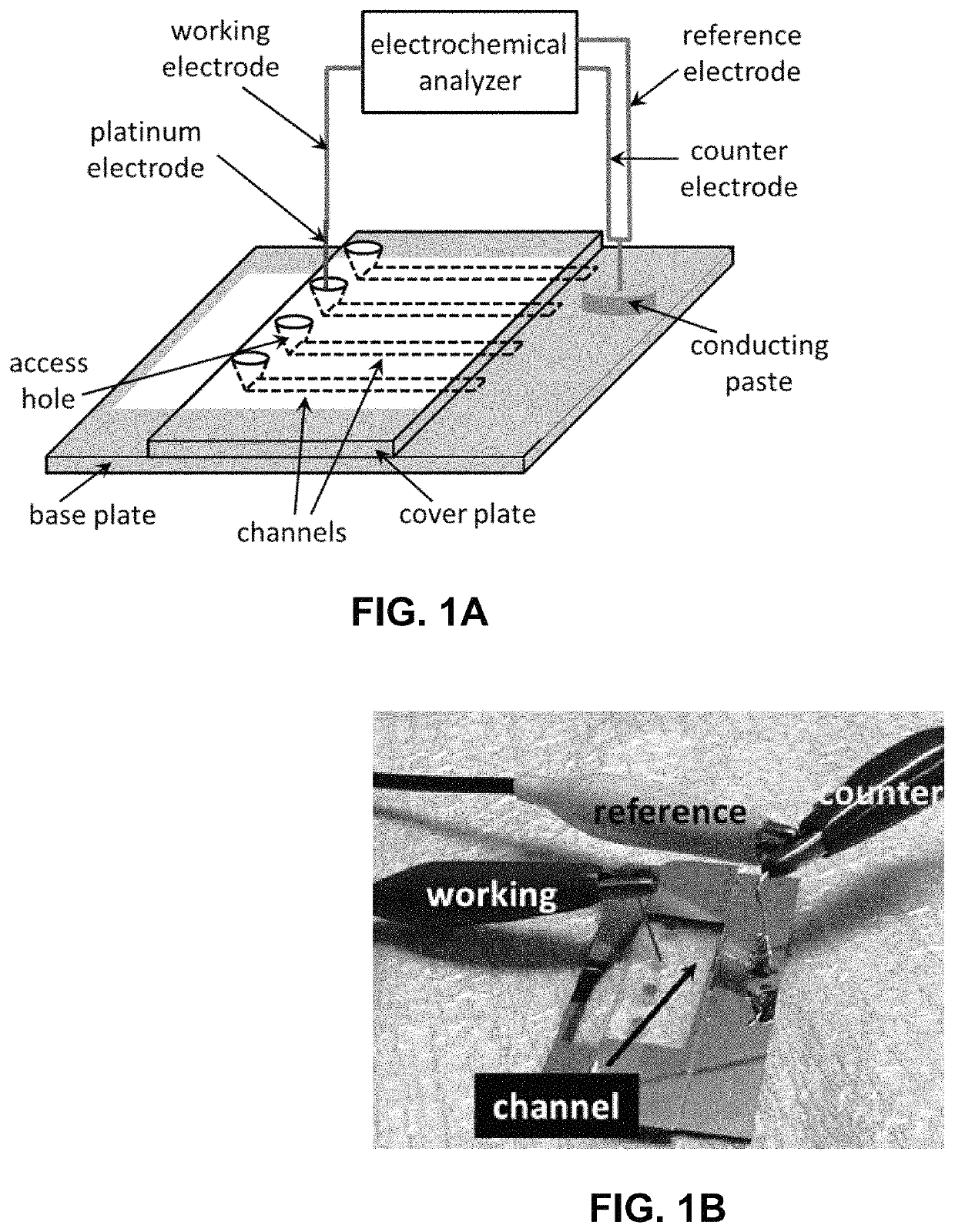
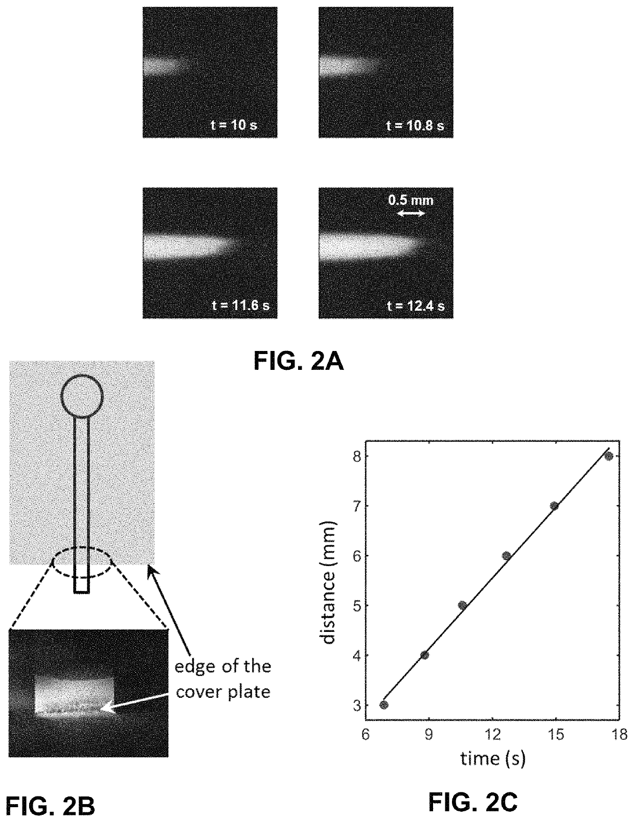
[0064]The use of external pumps or pressurized vessels to drive electrolytes through micro- and nano-fluidic channels presents a significant limitation in the practical use of fluidic batteries that operate based on the streaming current / potential phenomenon. The present disclosure addresses this limitation by employing spontaneous capillary flow to drive the noted transport process instead. An exemplary microfluidic electrochemical cell with an individual glass channel is fabricated to demonstrate such a battery with one of its channel terminals left open to the ambience to facilitate liquid evaporation. In this situation, a steady pressure-gradient can be produced and sustained in exemplary system through continuous vaporization of the solvent (water) at the open edge of the conduit driving the needed electrolyte flow. An electrochemical analyzer is employed to measure the electrical voltage and current produce...

example 2

l Power Generation in Micro- and Nanoscale Channels

[0107]In this example, we present example work with electrical power generation by fluidic means in micro- and nanoscale channels. The introduction of an electrolytic liquid (e.g., water) around a non-neutral solid surface leads to a distribution of electrical charges. In this situation, electrokinetic flow in the form of electro-osmosis or electrophoresis can be observed by applying a voltage across the channel terminals. Alternatively, it is possible to generate an electrical voltage across the terminals of a micro- or nanoscale channel by simply driving a fluid through it using pressure-gradient. This phenomenon occurs as the counter ions accumulated around the channel wall are transported by the pressure-driven flow causing a convection current, referred to as a streaming current. To maintain electrical neutrality at the channel terminals, a streaming potential between the two ends of the channel automatically develops yielding ...

example 3

l Energy Generation in Fluidic Channels and Membranes Using Spontaneous Capillary Flow

[0153]With the emergence of fluidic instrumentation, technologies enabling the precise transport of liquid samples through micro- and nanometer scaled structures have received significant attention from the research community. Such flows driven by electric / magnetic fields, acoustic waves, temperature gradients and surface tension among other forces have led to the development of several novel approaches to molecular separation, analyte sensing, material synthesis and energy generation methods that keep pushing scientific boundaries. One such effort focuses on the development of fluidic batteries which run by transporting electrolyte solutions around electrically charged surfaces using a pressure-drive. Electrolyte flow through a channel with a net surface charge produces an electrical current (streaming current) due to migration of the counter-ions in the Debye layer. This phenomenon causes a charg...


PUM

PropertyMeasurementUnit
diameteraaaaaaaaaa
lengthaaaaaaaaaa
lengthaaaaaaaaaa

Abstract

Described herein are systems and methods for the generation of electric current and / or electric potential utilizing micro- or nano-channels and capillary flow, including fluidic or microfluidic batteries and electrochemical cells. The provided systems and methods use capillary force to promote fluid flow through micro- and nano-fluidic channels by evaporating fluid at one terminus of the channel, and the resulting fluid flow generates electric potential and or current. Advantageously, the described systems and methods remove the need for pressurized vessels or external pumps, increasing net energy generation and decreasing complexity and size of potential fluidic batteries.

Description

CROSS-REFERENCE TO RELATED APPLICATIONS[0001]This application claims the benefit of priority of U.S. Provisional Application Ser. No. 62 / 562,928 filed Sep. 25, 2017, which is hereby incorporated by reference in its entirety, to the extent not inconsistent herewith.BACKGROUND OF INVENTION[0002]Advances in fluidic techniques enabling precise control over liquid transport in micro- and nano-fluidic channels have spurred the development of fluidic battery devices which convert fluid motion into electrical power. Fluidic batteries are attractive as inexpensive, miniature and portable sources of electrical power for a variety of applications. Moreover, the life-cycle of fluidic batteries, from fabrication to end-of-life, may have a minimal environmental footprint, due to the absence of combustion of fossil fuels and, in some cases, batteries which do not require rare or toxic materials.[0003]Fluidic batteries take advantage of an electrokinetic phenomenon called “streaming potential,” or ...

Claims


Application Information

Patent Timeline
Patent Type & Authority Patents(United States)
IPC IPC(8): H01M10/04H01M2/38H01M4/60H01M8/04089H01M8/04186H01M4/02
CPCH01M10/04H01M2/38H01M4/602H01M8/04089H01M8/04186H01M2004/021H01M2010/0495Y02E60/50Y02E60/10Y02P70/50H01M14/00H01M50/70
Inventor DUTTA, DEBASHIS
Owner UNIVERSITY OF WYOMING
Why Eureka
Try Eureka