Antenna coupler

a technology of couplers and antennas, applied in the structural form of antennas, non-resonant long antennas, antennas, etc., can solve the problems of different frequency ranges of mobile-radio devices, part of the hardware of mobile-radio devices used in testing, etc., and achieve the effect of low rippl

Active Publication Date: 2010-10-28
ROHDE & SCHWARZ GMBH & CO KG
View PDF8 Cites 8 Cited by
  • Summary
  • Abstract
  • Description
  • Claims
  • Application Information

AI Technical Summary

Benefits of technology

[0017]It is particularly advantageous to provide an absorber material on the reflector, of which the maximum thickness is one third of the spacing distance between the reflector and the printed-circuit board. By particular preference, with a spacing distance between the reflector and

Problems solved by technology

However, this has the disadvantage, that only a part of the hardware of the mobile-radio device is used in the test.
One problem in this context is that different mobile-radio devices operate in different frequency ranges.
With the proposed spiral antenna

Method used


Image

  • Antenna coupler
  • Antenna coupler
  • Antenna coupler

Examples


Embodiment Construction

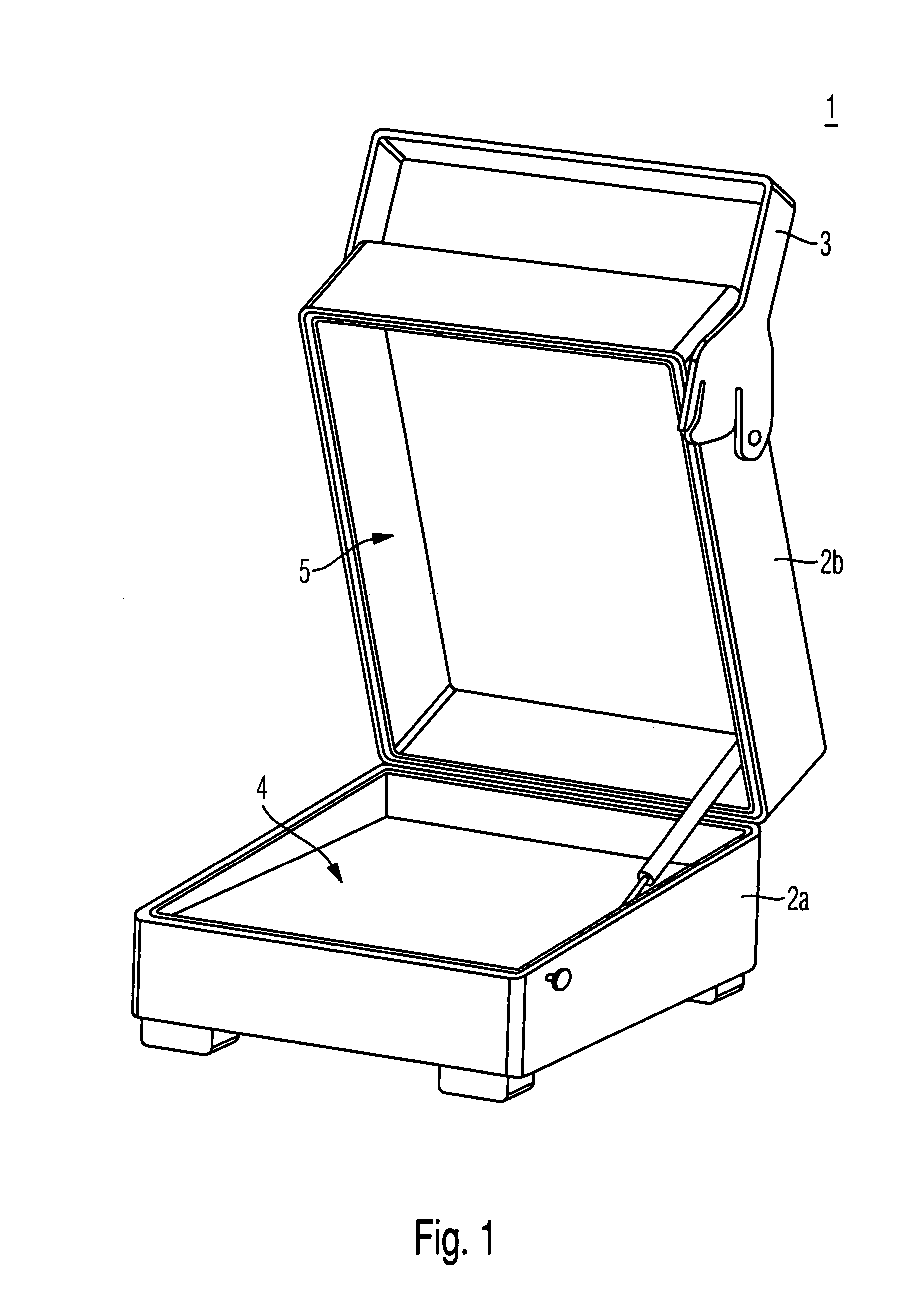
[0032]FIG. 1 shows a housing 1 of an antenna coupler. The housing 1 provides a lower part 2a and a cover part 2b. The lower part 2a and the cover part 2b are connected to one another in an articulated manner. The lower part 2a is open at one side and surrounds a first volume 4. At least the printed-circuit board, on which the coupling structures are formed, is inserted into this first volume 4, in which only a flat board is inserted in FIG. 1.

[0033]A second volume is similarly formed in the cover part 2b. This second volume 5 is empty in the illustrated embodiment of the housing 1. However, it is equally conceivable that the second volume 5 is filled with an absorber material. For example, pyramidal structures can be formed in an absorbing material, wherein the entire absorber element is attached to the cover part 2b. Furthermore, a closing mechanism 3 is formed on the cover part 2b. In the illustrated exemplary embodiment, this is rotatable and engages in a locking projection on th...


PUM


Abstract

An antenna coupler for testing a mobile-radio device with a coupling element formed in a flat manner by strip conductors on a printed-circuit board and with a retaining device formed on a first side of the printed-circuit board for positioning a mobile-radio device in the vicinity of the coupling element. On the first side of the printed-circuit board, at least one slit structure is introduced into an ground metallization formed there. For feeding the slit structure serving as the coupling element, at least one stripline formed on the second side facing away from it forms a microstripline with the ground metallization remaining between the slit structure of the first side.

Description

CROSS-REFERENCE TO RELATED APPLICATION[0001]The present application is a national phase application of PCT Application No. PCT / EP2008 / 010757, filed on Dec. 17, 2008, and claims priority to European Patent Application No. 07 024 557.6, filed on Dec. 18, 2007, and European Patent Application No. 08 008 065.8, filed on Apr. 25, 2008, the entire contents of which are herein incorporated by reference.BACKGROUND OF THE INVENTION[0002]1. Field of the Invention[0003]The invention relates to an antenna coupler for testing a mobile-radio device.[0004]2. Discussion of the Background[0005]For the testing of mobile-radio devices, it was formerly conventional to provide a separate connection to the mobile-radio device, by means of which the mobile-radio device is connected to test device. However, this has the disadvantage, that only a part of the hardware of the mobile-radio device is used in the test. Accordingly, the transmission of the signals is not implemented, for example, via the radio in...

Claims


Application Information

Patent Timeline
IPC IPC(8): H01Q9/02
CPCH01Q9/27H01Q11/10H01Q11/105H01Q19/106H01Q13/106H01Q19/10H01Q13/10
Inventor ROTH, MARTINHOLZMANN, GOTTFRIEDSCHIESSL, ANDREAS
Owner ROHDE & SCHWARZ GMBH & CO KG
Why Eureka
Try Eureka