
Semiconductor device and drive recorder using same

Active Publication Date: 2010-10-28
ROHM CO LTD
View PDF5 Cites 22 Cited by
  • Summary
  • Abstract
  • Description
  • Claims
  • Application Information

AI Technical Summary

Benefits of technology

[0010]FIG. 301 is a block diagram showing another example of the conventional semiconductor device connected to a plurality of devices through a bus. FIG. 302 is a diagram showing the setting range of an interface voltage in the semiconductor device of FIG. 301. As shown in FIGS. 301 and 302, a voltage conversion interface IC (level shifter IC) is used to level shift the recommended range (operation guaranteed range) of the interface voltage of the external device C, and thus it is possible to extend the allowable range of the interface voltage set in the bus. However, in this type of configuration, the voltage conversion interface IC (level shifter IC) is additionally required, and this disadvantageously increases the cost and the size of an appliance.
[0013]With the semiconductor device of the present invention, it is possible to easily connect a plurality of external devices having different interface voltages.

Problems solved by technology

Hence, when the external devices mentioned above are connected to the semiconductor device through a single bus, the allowable range of the interface voltage set in the bus is small, and thus it may be difficult to achieve the setting.
When, as shown in FIG. 300, the recommended range (operation guaranteed range) of the interface voltage is varied for each of external devices A, B and C, since the interface voltage of the bus needs to be set within a voltage range in which all the interface voltages of the external devices A, B and C overlap each other, the allowable range of the interface voltage set in the bus is small, and thus it is very difficult to achieve the setting.
Moreover, in order to stably operate a plurality of external devices, it is necessary to design, in an ingenious manner, circuits around the power supply of the semiconductor device (controller IC) and a printed circuit board (PCB), and this results in increased cost.
However, in this type of configuration, the voltage conversion interface IC (level shifter IC) is additionally required, and this disadvantageously increases the cost and the size of an appliance.

Method used


Image

  • Semiconductor device and drive recorder using same
  • Semiconductor device and drive recorder using same
  • Semiconductor device and drive recorder using same

Examples


Embodiment Construction

Outline

[0317]An outline of a silicon monolithic semiconductor integrated circuit device (hereinafter called the present LSI) disclosed in this specification will first be described. The present LSI is an image sound processing LSI that incorporates a central processing unit (hereinafter called a CPU).

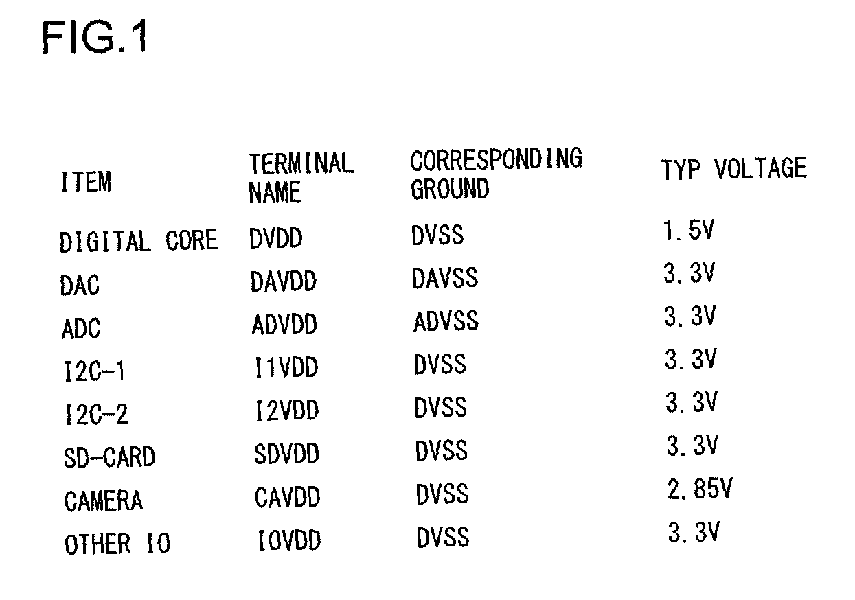
[0318]A feature of the present LSI will now be described. The present LSI is a one-chip LSI, for use in a drive recorder, that makes it easy to develop the drive recorder. The present LSI incorporates dedicated hardware that controls a triaxial acceleration sensor necessary for the drive recorder, a camera module, an SD card and the like. The dedicated hardware can be controlled by the CPU, and can perform various applications.

[0319]The present LSI incorporates the 32-bit CPU. The CPU has an instruction cache and a data cache, and an instruction tightly coupled memory and a data tightly coupled memory (hereinafter called a TCM). The data sizes of the instruction cache, the data cache, t...


PUM


Abstract

A semiconductor device of the present invention is provided with a terminal for connecting a plurality of buses to the outside of the semiconductor device, a bus interface circuit for treating the plurality of buses as the same bus within the semiconductor device and a controller connected to the bus interface circuit.

Description

CROSS-REFERENCE TO RELATED APPLICATIONS[0001]This application is based on Japanese Patent Application No. 2009-099940 filed on Apr. 16, 2009, the contents of which are hereby incorporated by reference.BACKGROUND OF THE INVENTION[0002]1. Field of the Invention[0003]The present invention relates to a semiconductor device to which a plurality of external devices are connected through a bus.[0004]2. Description of Related Art[0005]In recent years, the size, the consumption power and the like of circuits have been reduced, and thus the interface voltage of a semiconductor device (controller IC) connected to a plurality of external devices through a bus tends to be reduced. With this recent trend, in a plurality of external devices used as a system along with a semiconductor device for the market of mass-produced appliances, low voltages are used.[0006]One example of a conventional technology related to the foregoing (where a plurality of devices are connected to a single bus) is disclose...

Claims


Application Information

Patent Timeline
IPC IPC(8): H04N5/76G05F1/00H03L5/00
CPCH04N5/765H04N9/8042H04N5/907
Inventor MARUMOTO, KYOJIKUROTSUCHI, YUJI
Owner ROHM CO LTD
Learn More