
Image flow knowledge assisted latency-free in-loop temporal filter

Inactive Publication Date: 2010-10-28
SIGMA DESIGNS
View PDF6 Cites 6 Cited by
  • Summary
  • Abstract
  • Description
  • Claims
  • Application Information

AI Technical Summary

Benefits of technology

[0007]An object of the present invention is to provide methods for encoding images that minimize temporal noise.
[0008]Another object of the present invention is to provide methods for temporal smoothing that are efficient and scalable.
[0010]An advantage of the present invention is that it provides methods for encoding images that minimize temporal noise.
[0011]Another advantage of the present invention is that it provides methods for temporal smoothing that are efficient and scalable.

Problems solved by technology

Digital video sequences often suffer from random temporal noise, which is typically introduced during the capturing process by video acquisition device such as CCD / CMOS sensors.
Because of these issues, they are generally very expensive to encode and would substantially degrade coding efficiency.
Even when they are encoded, they generally degrade the perceptual quality of the reconstructed video.
However, this approach inevitably incurs latency overhead between input and encoding as well as memory overhead to store pre-determined motion vectors.
Both of these additional costs are generally undesirable for many consumer electronics applications.
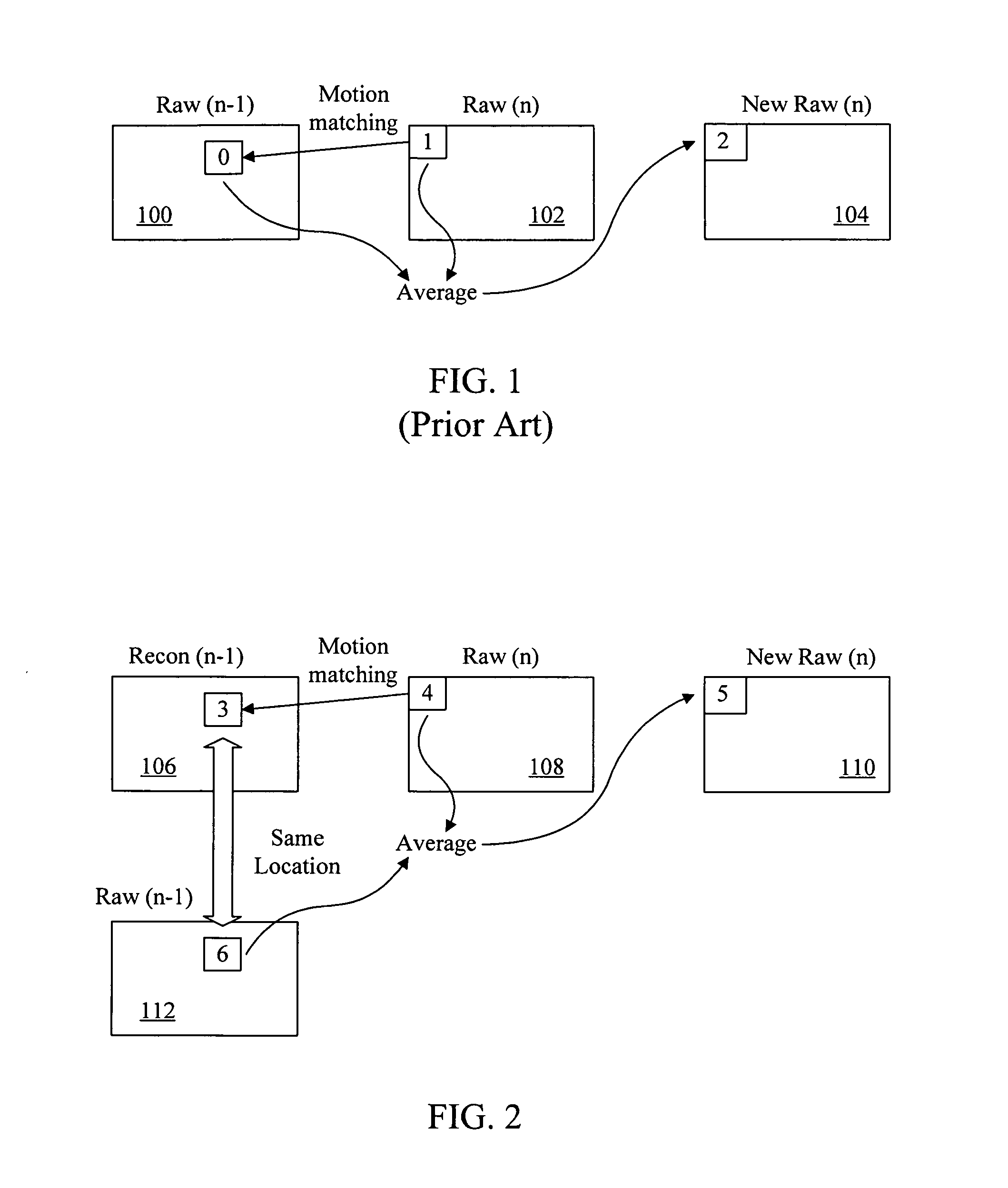
Although this approach is an improved one when compared with the first case in terms of latency and frame buffer overhead, however, it tends to suffer from deviation between motion vectors derived from raw-to-raw image motion matching and those based on recon-to-raw images due to recon quality degradation, especially at aggressive bit rates.
At such bit rates, recon images can deviate from corresponding raw images and therefore motion vectors calculated from raw-to-raw motion matching are not necessarily better than those derived based on recon-to-raw images in terms of coding efficiency and performance.
In such case, the usage of motion vectors calculated based on raw-to-raw motion matching for actual motion compensation generally produces poor recon movies.

Method used


Image

  • Image flow knowledge assisted latency-free in-loop temporal filter
  • Image flow knowledge assisted latency-free in-loop temporal filter
  • Image flow knowledge assisted latency-free in-loop temporal filter

Examples


Embodiment Construction

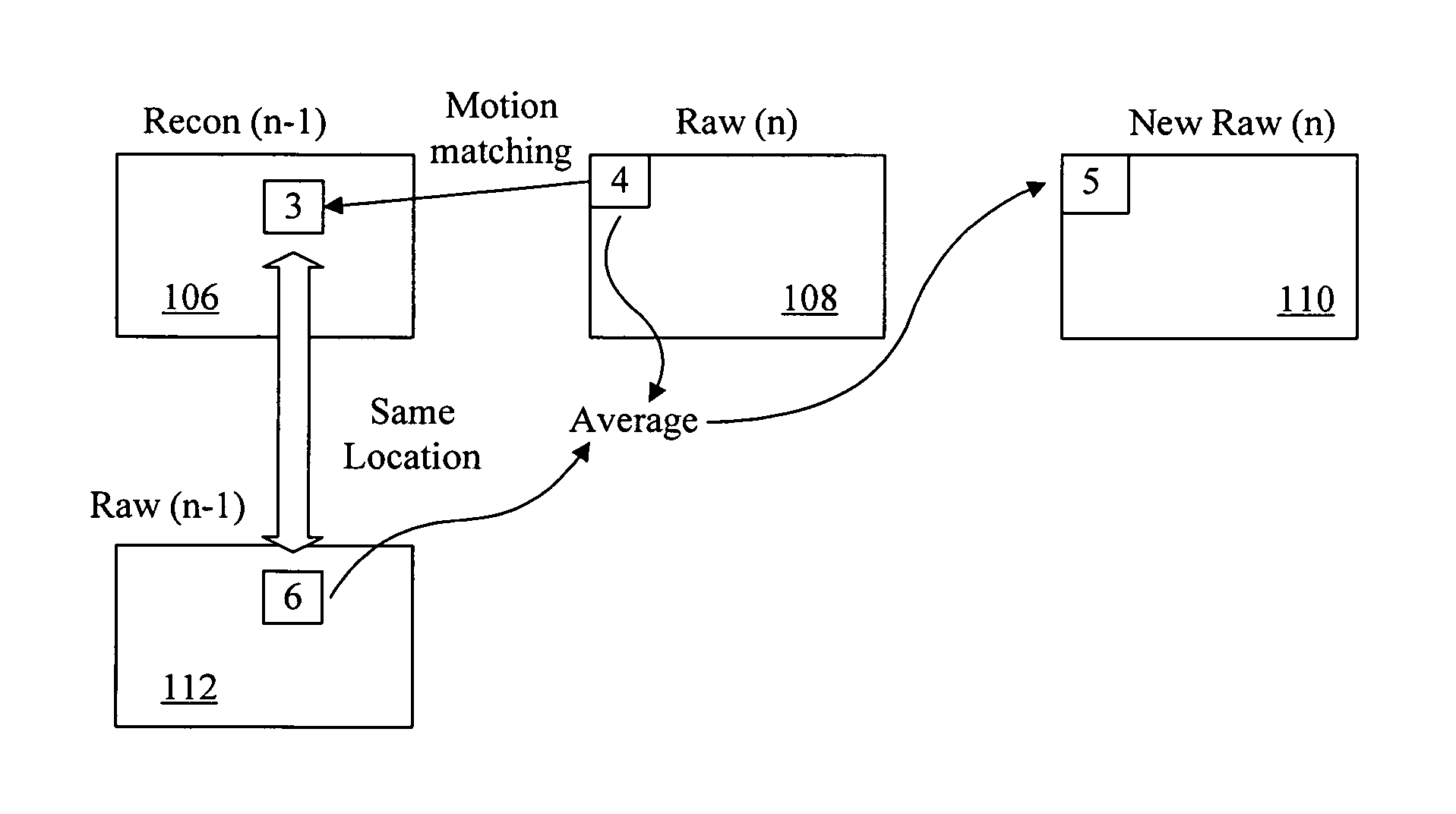
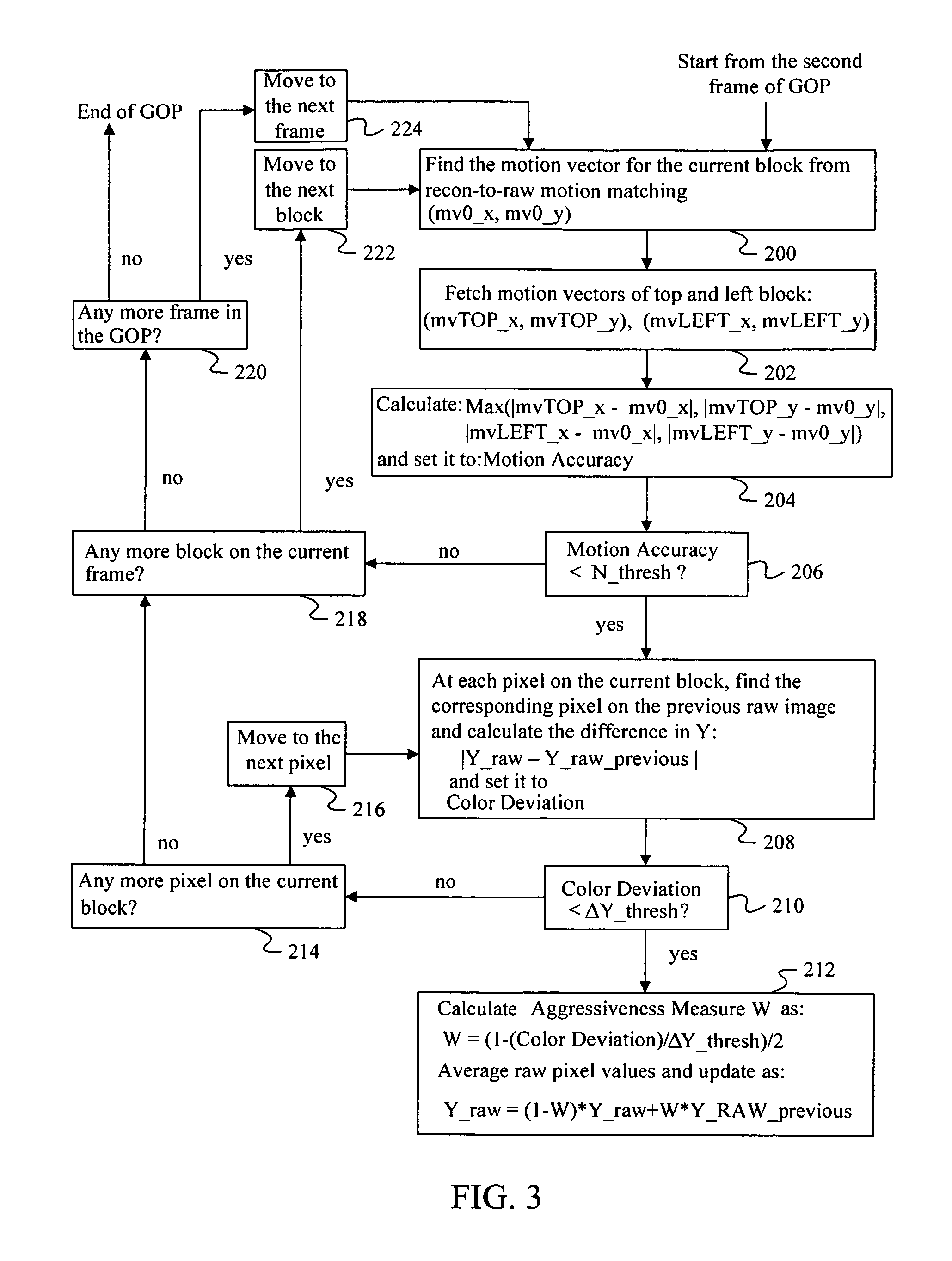
[0016]The presently preferred methods of the present invention provide methods that use motion vectors calculated from recon-to-raw motion matching for temporal smoothing. For the purpose of this application, “raw” is commonly referred to as images received from “input” to the engine, which performs temporal smoothing as well as encoding / trans-coding operation, and “recon” is commonly referred to as images received from “output” and has already undergone encoding / trans-coding process by the engine and has been reconstructed to be used as reference pictures for the purpose of inter-picture prediction as part of encoding / trans-coding process. This approach not only enables an implementation where improved latency and reduced frame buffer size are realized, but also leads to a scalable performance which is built into its underlying algorithm structure.

[0017]At very high bit rates, since recon images are closer to raw images, the preferred methods tend to behave like approaches based on...


PUM


Abstract

Digital image acquisition device such as CCD / CMOS sensors often introduces random temporal noise into digital video sequences. Temporal noise generally carries high frequency components in both the spatial and temporal domains and is also random in nature. Because of these properties, they are generally very expensive to encode and would substantially degrade coding efficiency. It is therefore important to eliminate or suppress such temporal noise in video inputs prior to encoding. The present invention provides a methodology to achieve such a goal in a highly cost-effective manner where coding performance, latency, computational cost, and memory requirements are optimized. This methodology can be efficiently implemented as part of digital video compression algorithm and scales nicely for various bitrates.

Description

CROSS REFERENCE[0001]This application is a Continuation-In-Part of application Ser. No. 11 / 166,705, filed on Jun. 23, 2005, which claims priority from a United States provisional patent application entitled “Image Flow Knowledge Assisted Latency-Free In-loop Temporal Filter” filed on Jun. 23, 2004, having an application No. 60 / 582,426. This provisional patent application is incorporated herein by reference.FIELD OF INVENTION[0002]This invention relates to digital video compression algorithms as well as digital signal filtering algorithms, in which digital signal filtering is applied to input images.BACKGROUND[0003]Digital video sequences often suffer from random temporal noise, which is typically introduced during the capturing process by video acquisition device such as CCD / CMOS sensors. Temporal noise generally carries high frequency components in both the spatial and temporal domains and is also random in both spatial and temporal domains. Because of these issues, they are genera...

Claims


Application Information

Patent Timeline
IPC IPC(8): H04N7/26
CPCH04N5/145H04N19/139H04N19/176H04N19/51H04N19/198H04N19/117H04N19/17H04N19/184H04N19/196
Inventor WATANABE, HITOSHI
Owner SIGMA DESIGNS
Learn More