Cutting Tool and a Process for making Such a Cutting Tool

a cutting tool and cutting technology, applied in the field of drills, can solve the problems of insufficient display of the characteristics of the first material and the cover of parts

Active Publication Date: 2010-10-28
ISCAR LTD
View PDF7 Cites 18 Cited by
  • Summary
  • Abstract
  • Description
  • Claims
  • Application Information

AI Technical Summary

Benefits of technology

[0046]The blade may cut in a directi...

Problems solved by technology

Thus, even unnecessary parts are covered, and the characteristics of the first materia...

Method used


Image

  • Cutting Tool and a Process for making Such a Cutting Tool
  • Cutting Tool and a Process for making Such a Cutting Tool
  • Cutting Tool and a Process for making Such a Cutting Tool

Examples


Embodiment Construction

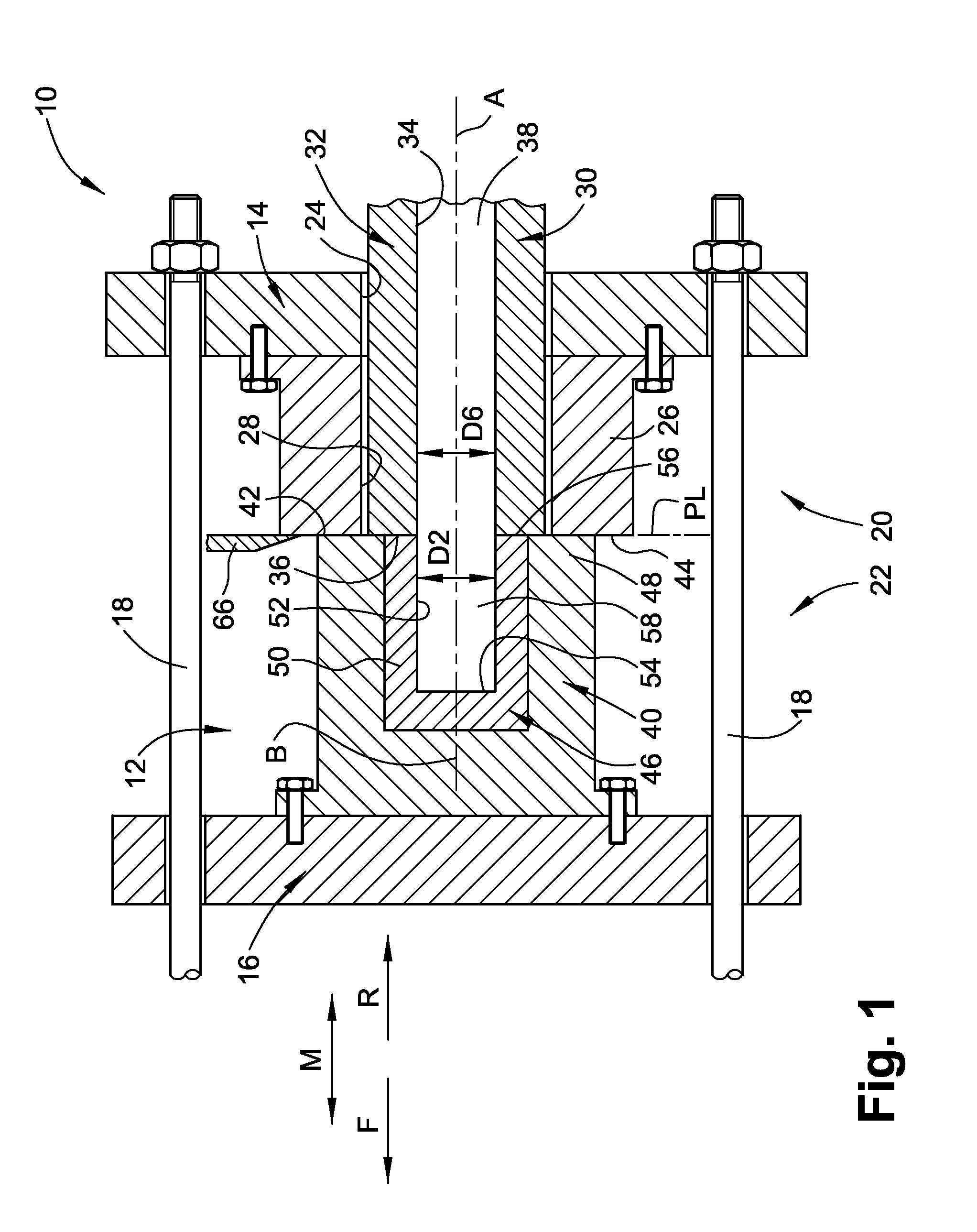
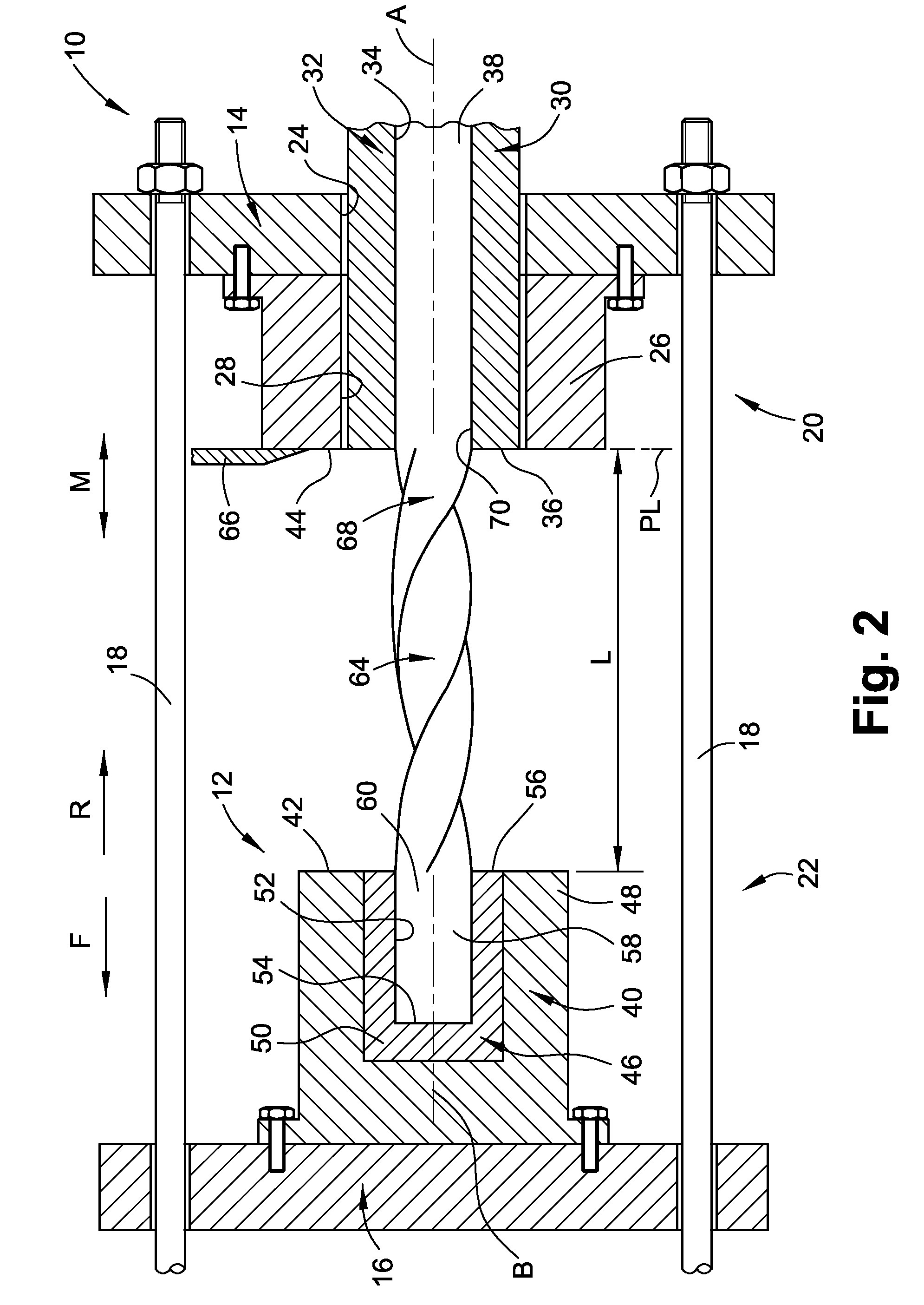
[0083]Attention is first drawn to FIG. 1, showing an injection and extruding system 10 in accordance with the present invention. The injection and extruding system 10 (hereinafter referred to as the “system”) comprises basic components of an injection machine 12 as known in the art. However, the system 10 provides a process of manufacturing a product that combines both an injection molding process and an extrusion process as will be later described. For the sake of clarity, it should be understood that the term an “injection machine” is also known as an “injection molding machine” where molten material is injected into a cavity of a mold.

[0084]The system 10 comprises a fixed plate 14 that is connected to a movable plate 16 by means of tie bars 18. Typically, the system 10 comprises four tie bars 18 that are parallel to each other and enable sliding of the movable plate 16 along a bidirectional movement direction M that is perpendicular to the fixed plate 14.

[0085]The system 10 is no...


PUM

PropertyMeasurementUnit
Lengthaaaaaaaaaa
Material propertiesaaaaaaaaaa

Abstract

A cutting tool having a monolithic construction includes an injection molded shank, and an extruded fluted portion extending forwardly from the shank, the shank and the fluted portion having a monolithic construction. The process for making the cutting tool includes forming a cutting tool green body by injection molding a shank of the green body and extruding a fluted portion of the green body such that the shank and the fluted portion have a monolithic construction; and then sintering the cutting tool green body.

Description

FIELD OF THE INVENTION[0001]The present invention relates to the field of cutting tools that are made by a continuous and uninterrupted injection and extrusion process, and more specifically, to the field of drills that are made by such an injection and extrusion process.BACKGROUND OF THE INVENTION[0002]The use of an extrusion process for the production of cutting tools made of cemented carbide is known. There are several types of cutting tools that may be produced by such a process, e.g., drills, end mills, reamers, taps, as well as countersinking and counterboring tools. The required cutting tool may be extruded to the desired diameter and length, and then, the necessary chip evacuation flutes are produced.[0003]In some cases, the chip evacuation flutes may be parallel to a longitudinal axis of the cutting tool, as required, for example, in some kinds of reamers. In other cases, the chip evacuation flutes may extend spirally around the longitudinal axis, as required, for example, ...

Claims


Application Information

Patent Timeline
IPC IPC(8): B23B51/06B23B51/02B23P15/32B23P23/00
CPCB21C23/147Y10T408/455B22F2998/00B23B51/02B23B51/06B23P15/32B22F2005/001Y10T29/49988Y10T408/907Y10T408/9097B22F3/225B22F3/20B21C23/14B23P17/02
Inventor SHAVIT, AMOS
Owner ISCAR LTD
Why Eureka
Try Eureka