
Fluid replacement device

a technology replacement device, which is applied in the field of flue gas management system, can solve the problems of insufficient hydration of patients, inability of attending nurses to learn complex systems, and inability to accommodate separate urine drop counters, weight scales, or “networked” units, etc., and achieve the effect of hydrating patients sufficiently

Active Publication Date: 2010-10-28
CARDIORENAL SYST INC
View PDF93 Cites 12 Cited by
  • Summary
  • Abstract
  • Description
  • Claims
  • Application Information

AI Technical Summary

Benefits of technology

[0007]Accordingly, it is desirable to hydrate the patient sufficiently to encourage the patient to urinate and expel the toxic contrast agent and also to infuse the patient with fluid to balance the urine expelled by the patient with the fluid infused into the patient so that the patient does not become dehydrated.
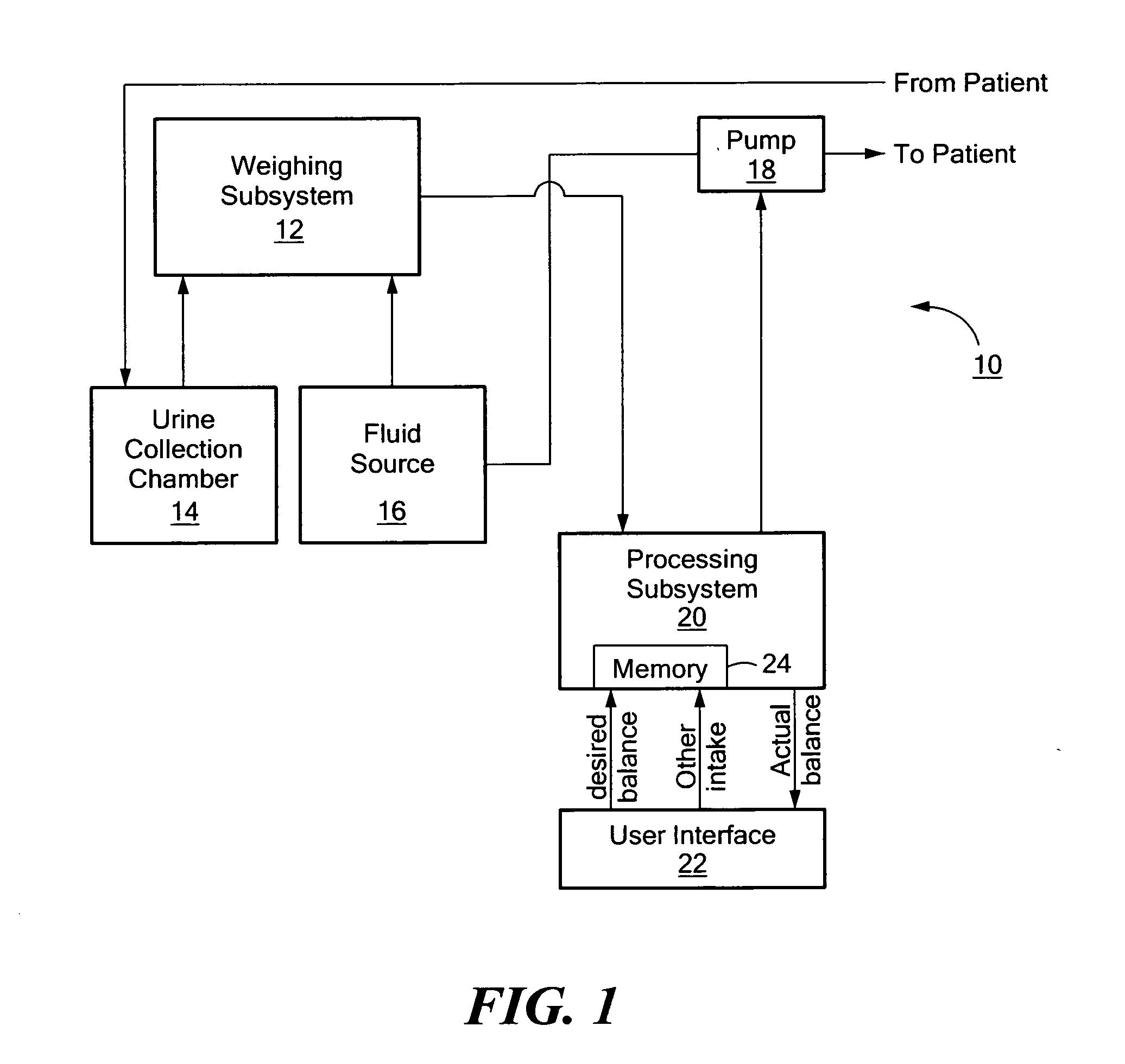
[0011]A fluid replacement device in accordance with an example of the invention includes a console with a weighing subsystem responsive to a first fluid source and a urine collection chamber, and a pump configured to pump fluid from the first fluid source into a patient. A processing subsystem in the console is responsive to the weighing subsystem and is configured to determine, based on the weight of the first fluid source and the weight of the urine collection chamber, the patient's urine output and the amount of fluid infused into the patient from the first fluid source. The processing subsystem is further configured to control the pump to adjust the operation of the pump based on the patient's urine output and the amount of fluid infused into the patient. A user interface in the console allows the user to set a desired fluid balance for the patient and to set an amount of at least one additional fluid delivered to the patient. The processing subsystem is responsive to these settings and is further configured to automatically calculate the patient's actual fluid balance based on the determined urine output, the determined amount of fluid infused into the patient from the first fluid source, and the set amount of the at least one additional fluid delivered to the patient. The pump is controlled based on the actual fluid balance and the set desired fluid balance until the actual fluid balance is the same as or approximately the same as the desired fluid balance.
[0016]One novel fluid replacement device comprises a console including a pump infusing fluid from a first fluid source into a patient, and a processing subsystem configured to determine the patient's urine output and the amount of fluid infused into the patient from the first fluid source. The processing subsystem is also configured to control the pump to adjust the operation of the pump based on the patient's urine output and the amount of fluid infused into the patient. A user interface in the console allows the user to set a desired fluid balance for the patient and set an amount of at least one additional fluid delivered to the patient. The processing subsystem is responsive to these setting and automatically calculates the actual fluid balance based on the determined urine output, the determined amount of fluid infused into the patient from the first fluid source, and the set amount of the at least one additional fluid delivered to the patient. The pump is controlled based on the actual fluid balance and the set desired fluid balance until the actual fluid balance is the same as or approximately the same as the desired fluid balance.

Problems solved by technology

But, the cath lab and other surgical and recovery sites are too small and crowded to accommodate separate urine drop counters, weight scales, or “networked” units.
Moreover, the attending nurses do not have the time to learn complex systems.
This is perhaps why the proposed systems of the prior art have not been commercially successful.

Method used


Image

  • Fluid replacement device
  • Fluid replacement device
  • Fluid replacement device

Examples


Embodiment Construction

[0037]Aside from the preferred embodiment or embodiments disclosed below, this invention is capable of other embodiments and of being practiced or being carried out in various ways. Thus, it is to be understood that the invention is not limited in its application to the details of construction and the arrangements of components set forth in the following description or illustrated in the drawings. If only one embodiment is described herein, the claims hereof are not to be limited to that embodiment. Moreover, the claims hereof are not to be read restrictively unless there is clear and convincing evidence manifesting a certain exclusion, restriction, or disclaimer.

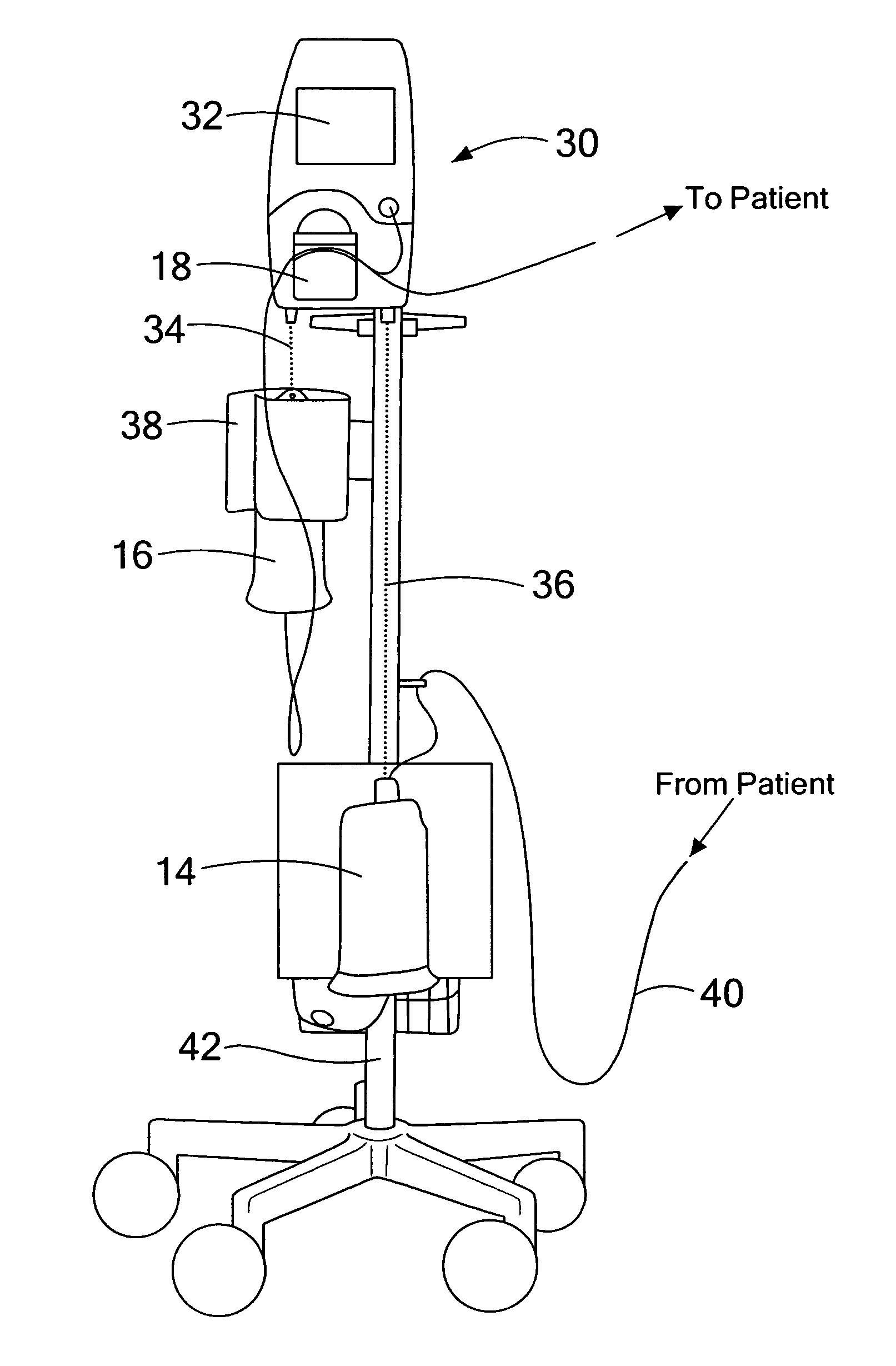
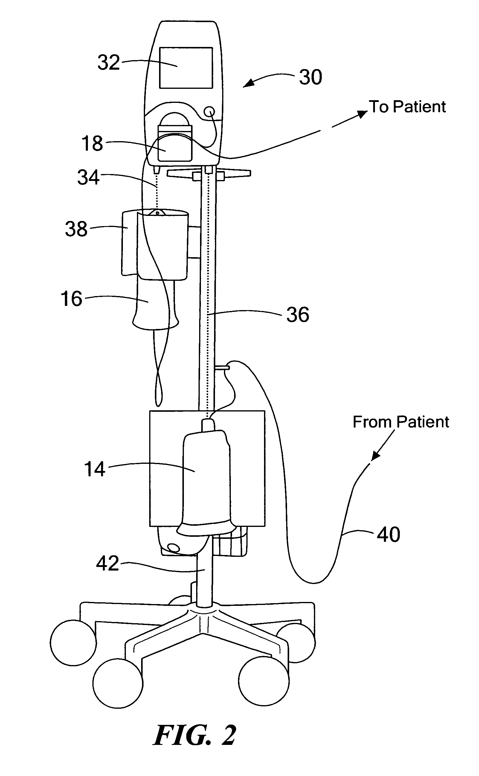
[0038]Fluid replacement system 10, FIG. 1, in one example, includes weighing subsystem 12 responsive to both the weight of urine collection chamber 14 and source of fluid 16.

[0039]Pump 18 is configured to pump fluid from source 16 into a patient as shown. Pump 18 is controlled by processing subsystem 20, e.g., a computer, a...


PUM


Abstract

A fluid replacement device and method. A console includes a weighing subsystem responsive to a first fluid source and a urine collection chamber. A pump is configured to infuse fluid from the first fluid source into a patient. A processing subsystem in the console is responsive to the weighing subsystem. Based on the weight of the first fluid source and the weight of the urine collection chamber, the patient's urine output and the amount of fluid infused into the patient from the first fluid source are determined. A user interface in the console allows the user to set a desired fluid balance for the patient and the amount of at least one additional fluid delivered to the patient. An actual fluid balance is calculated based on the determined urine output, the determined amount of fluid infused into the patient from the first fluid source, and the set amount of the at least one additional fluid delivered to the patient. The pump is controlled based on the actual fluid balance and the set desired fluid balance so the actual fluid balance becomes the same as or approximately the same as the desired fluid balance.

Description

RELATED APPLICATIONS[0001]This application hereby claims the benefit of and priority to U.S. Provisional Application Ser. No. 61 / 206,254, filed on Jan. 28, 2009 under 35 U.S.C. §§119, 120, 363, 365, and 37 C.F.R. §1.55 and §1.78.FIELD OF THE INVENTION[0002]The subject invention relates to fluid management systems.BACKGROUND OF THE INVENTION[0003]Systems have been proposed to automatically measure the fluid delivered to a patient and fluids expelled or taken from a patient.[0004]U.S. Pat. No. 4,291,692, for example, discloses and IV drop counter, a urine drop counter, and a microcomputer controlling an infusion pump. U.S. Pat. No. 7,029,456 discloses a “networked” system with no less than four separate units. See also U.S. Pat. No. 4,994,026 disclosing separate load scales and a control unit primarily used for dialysis.[0005]In a cath lab, for example, a patient has a contrast agent injected into his veins, the patient's vessels are imaged, and a therapy is administered, e.g., a sten...

Claims


Application Information

Patent Timeline
IPC IPC(8): A61M5/168G16H20/17G16H40/60G16Z99/00
CPCA61B5/20A61B5/4839G06F19/3468A61M5/1723A61M2202/0496A61B19/56A61B34/25G16H40/60G16H20/17G16Z99/00
Inventor DA SILVA, J. RICARDOGRONEK, WIESLAWHALPERT, ANDREW V.RUDKO, ROBERT I.TAUSCHER, MARK
Owner CARDIORENAL SYST INC
Learn More