
Mobile Electronic Device and Method for Controlling the Same

a technology of electronic devices and mobile terminals, applied in the direction of measurement devices, substation equipment, instruments, etc., can solve the problem that the expected operation of mobile terminal devices cannot be guaranteed, and achieve the effect of accurately and clearly displaying the life of batteries

Inactive Publication Date: 2010-10-28
KYOCERA CORP
View PDF5 Cites 10 Cited by
  • Summary
  • Abstract
  • Description
  • Claims
  • Application Information

AI Technical Summary

Benefits of technology

The present invention relates to a portable electronic device with a rechargeable battery and a method for controlling it. The device includes an output unit that displays information on the life of the battery, which is useful for ensuring the battery operates correctly and can be used for a longer period of time. The device measures the voltage of the battery and uses a weighting value to determine the number of times charging has occurred. This allows the device to accurately and clearly display the life of the battery, and the user can be aware of the expected operation of the device. The invention provides a simple and cost-effective solution for accurately and clearly displaying the life of a battery in a portable electronic device.

Problems solved by technology

In addition, beyond this state, the expected operation of the mobile terminal device cannot be guaranteed due to an increase of internal resistance, etc.

Method used


Image

  • Mobile Electronic Device and Method for Controlling the Same
  • Mobile Electronic Device and Method for Controlling the Same
  • Mobile Electronic Device and Method for Controlling the Same

Examples


Embodiment Construction

[0055]A description is provided hereinafter regarding an embodiment of the present invention.

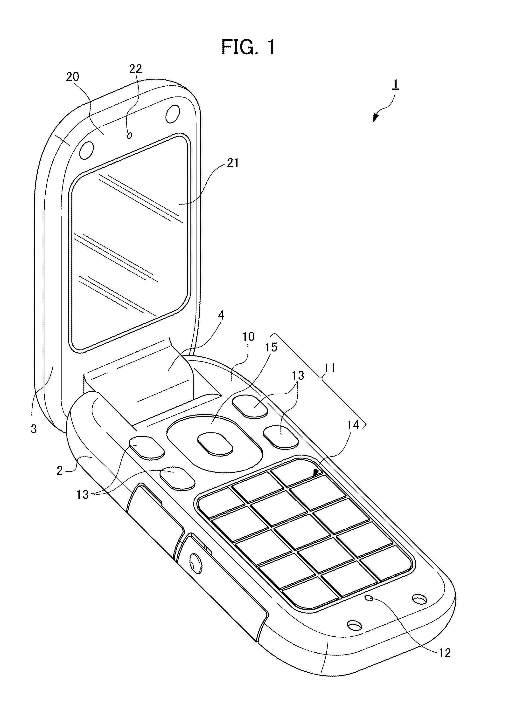
[0056]FIG. 1 is a perspective view showing an appearance of a cellular telephone device 1 as an example of a portable electronic device according to the present invention. It should be noted that, although a cellular telephone device is described hereinafter, the present invention is not limited thereto, and may be a PHS (Personal Handyphone System), a PDA (Personal Digital Assistant), a portable navigation device, a notebook PC or the like.

[0057]The cellular telephone device 1 is configured to include an operation unit side body 2 and a display unit side body 3. The operation unit side body 2 is configured to include on a front face 10 thereof an operation button set 11 and a microphone 12 to which sounds, which a user of the cellular telephone device 1 produces during a phone call, are input. The operation key set 11 includes: feature setting operation buttons 13 for operating various sett...


PUM


Abstract

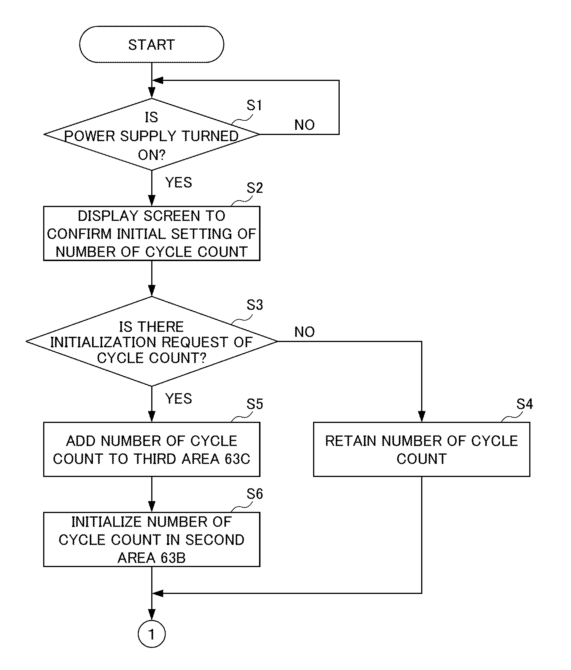
It is possible to provide a mobile electronic device which can accurately and clearly display a cell service life and a method for controlling the device.The mobile electronic device includes: a charge cell (32); a voltage measuring unit (system IC 64) which is connected to the charge cell (32) and measures a voltage of the charge cell (32); an output unit (display 21) which outputs various information; a memory (63) which stores a weighting value for each of voltage values; and a control unit (system IC 64) which measures a voltage of the charge cell (32) by the voltage measuring unit upon each start and end of charge of the charge cell (32), extracts a weighting value corresponding to the measured voltage value from the memory (63), successively adds the extracted weighting values so as to identify information on a number of charge times, and stores the information in the memory (63). The control unit causes the output unit to output information on a service life of the charge cell (32) according to the information on the number of charge times stored in the memory (63).

Description

TECHNICAL FIELD[0001]The present invention relates to a portable electronic device to which a rechargeable battery is mounted, and particularly relates to a portable electronic device that outputs information on life of a rechargeable battery, and a method of controlling the same.BACKGROUND ART[0002]Although lithium ion batteries are the current mainstream of batteries for cellular phones, due to the ever-increasing trend toward smaller sizes, lighter weight and higher functionality of mobile terminal devices (such as for continuously viewing a digital television program, continuously playing music, browsing WEB sites, etc.), it is anticipated that the cycle of charging and discharging a battery will be accelerated, and as a result, the life of a battery will tend to be shortened relative to the period of use of a mobile terminal device.[0003]Here, methods of detecting the life of a battery include a method in which the life of a battery is determined by way of a change in an impeda...

Claims


Application Information

Patent Timeline
Patent Type & Authority Applications(United States)
IPC IPC(8): G01R31/36
CPCG01R31/3679H04M1/72519G01R31/3682G01R31/392G01R31/3646H04M1/724
Inventor KOYAMA, AKIRAHAYAKAWA, TAKANOBUNAKAJIMA, MASAYOSHI
Owner KYOCERA CORP
Learn More