
Power supply capable of automatically monitoring service life and method for monitoring service life of power supply

An automatic monitoring and power supply technology, applied in the direction of power supply testing, measuring electricity, measuring electrical variables, etc., can solve problems such as errors, difficult power supply life estimation, and ripple current value monitoring difficulties, and achieve the effect of avoiding losses

Inactive Publication Date: 2013-05-01
HONG FU JIN PRECISION IND (SHENZHEN) CO LTD +1
View PDF1 Cites 8 Cited by
  • Summary
  • Abstract
  • Description
  • Claims
  • Application Information

AI Technical Summary

Problems solved by technology

However, in actual situations, it is very difficult to monitor the ripple current value of the electrolytic capacitor, and when the circuit of the power supply is fixed, the change of the ripple current value of the electrolytic capacitor in the power supply is small, and it can generally be regarded as In addition, even if the ripple current value can be accurately monitored, the estimation is based on the relationship between the ripple current value at the actual ambient temperature and the rated ripple current value of the power supply at an ambient temperature of 25 degrees , but in actual use, there is often a large difference between the rated ripple current value given by the manufacturer and the rated current value of the power supply when the user actually uses it, so there is a certain error in the relationship itself. Therefore, It is difficult to accurately estimate the life of the power supply based on the ripple current value of the detected electrolytic capacitor

Method used


Image

  • Power supply capable of automatically monitoring service life and method for monitoring service life of power supply
  • Power supply capable of automatically monitoring service life and method for monitoring service life of power supply
  • Power supply capable of automatically monitoring service life and method for monitoring service life of power supply

Examples


Embodiment Construction

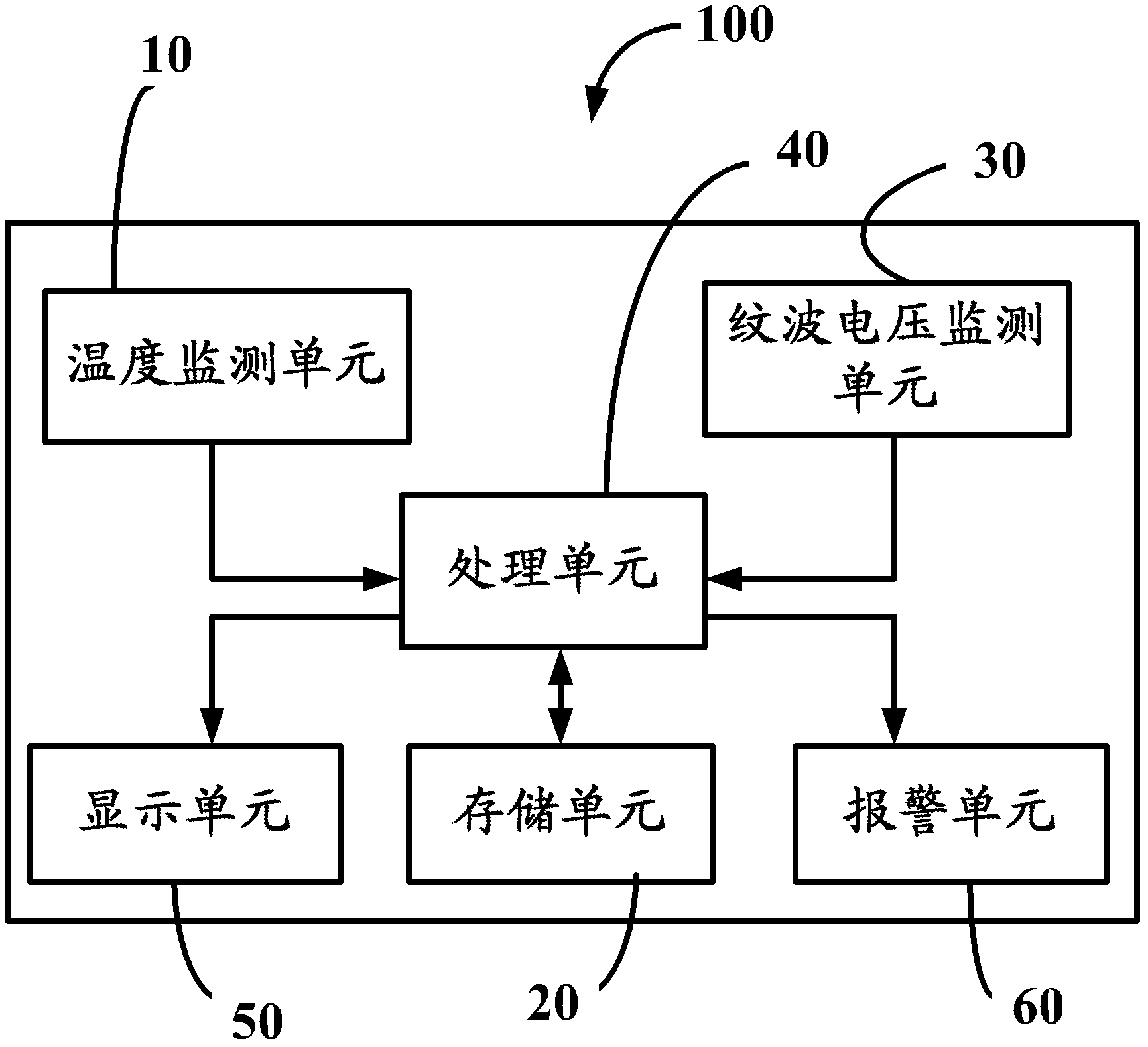
[0017] see figure 1 , is a schematic diagram of a power supply 100 capable of automatically monitoring service life in an embodiment of the present invention. Generally speaking, the ESR (Equivalent Series Resistance, Equivalent Series Resistance) value R of the power supply 100 is an important parameter indicating the life of the power supply 100. With the use of the power supply 100, the ESR value R of the power supply 100 will continue to increase. For the power supply 100 connected to the loop, the ripple current value I flowing through the electrolytic capacitor inside the power supply 100 does not change much, and generally can be considered approximately constant. Assuming that the ripple voltage value of the electrolytic capacitor inside the power supply 100 is U, according to the formula U=I*R, it can be known that the ripple voltage value U of the electrolytic capacitor inside the power supply 100 will increase continuously with the use of the power supply 100 . In ...


PUM


Abstract

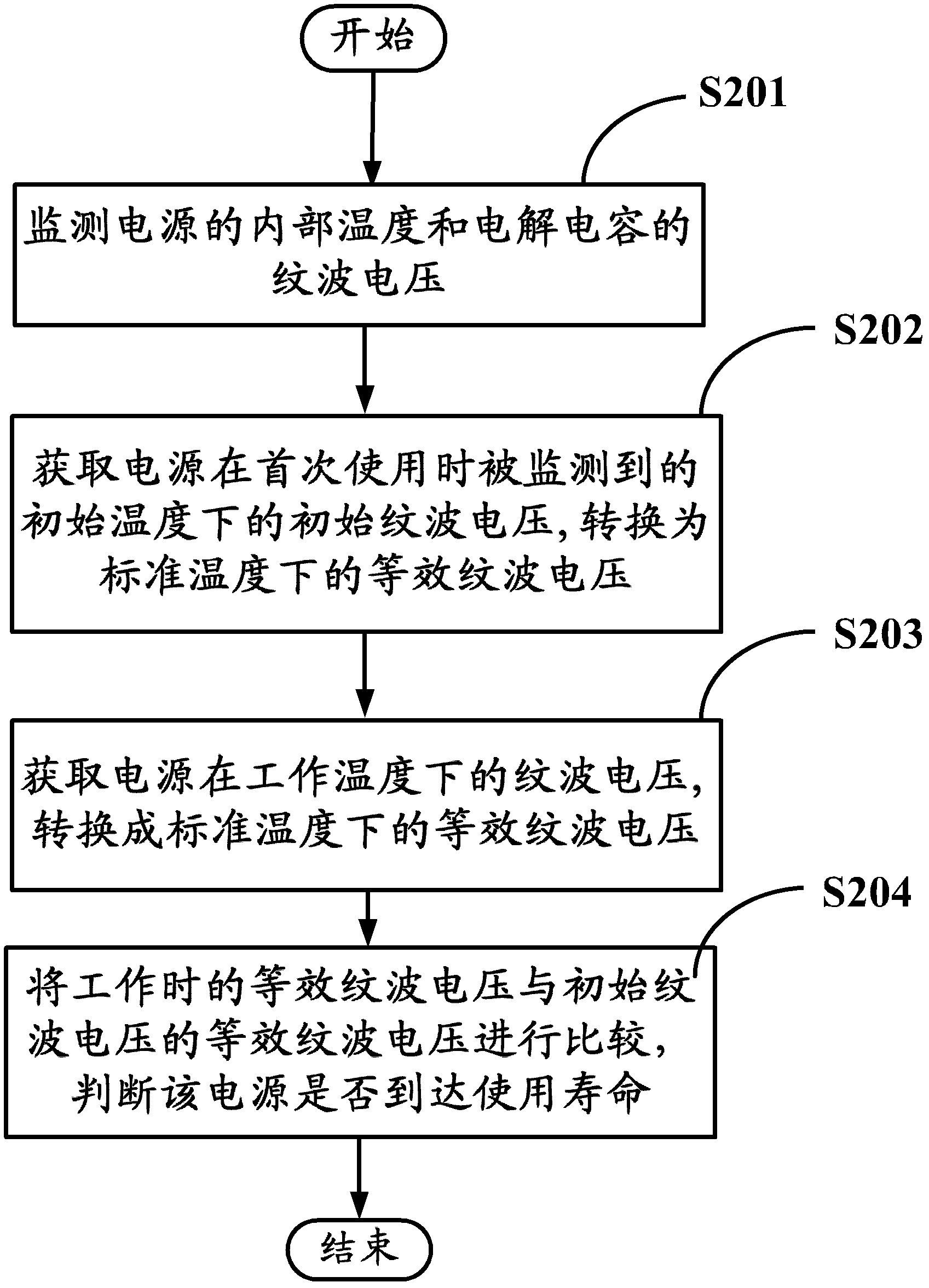
The invention discloses a power supply capable of automatically monitoring service life. The power supply comprises a temperature monitoring unit, a ripple voltage monitoring unit and a processing unit, wherein the temperature monitoring unit monitors the temperature inside the power supply, and the ripple voltage monitoring unit monitors ripple voltage of a power supply electrolytic capacitor. The processing unit acquires a ripple voltage in initial temperature and a ripple voltage in working temperature when the power supply is utilized at the first time, the ripple voltage in initial temperature and the ripple voltage in working temperature are converted into equivalent ripple voltages in standard temperature respectively, and the equivalent ripple voltage corresponding to the ripple voltage in process of working is compared with the equivalent ripple voltage corresponding to the initial ripple voltage so as to judge whether the power supply reaches the service life or not. The invention further relates to a method for monitoring the service life of the power supply, which can accurately monitor and estimate the power supply in operation conveniently, so that a user is promoted to avoid the loss caused by the unexpected power outage when the power supply is close to the service life.

Description

technical field [0001] The invention relates to a power supply capable of automatically monitoring the service life and a method for monitoring the service life of the power supply. Background technique [0002] In fields such as computers and electronic commerce, devices such as servers and storage devices are widely used, and power supplies are key components of these devices. The shutdown of equipment caused by unexpected power failure will cause great losses, even irreparable disasters. Therefore, the service life of the power supply should be monitored, so that users can be reminded in advance when the power supply is approaching its service life to prevent losses. [0003] As disclosed in the Chinese patent application document with the application number 201010156582.4 and the application date of April 27, 2010, the current general method of monitoring the service life of the power supply is to detect the ripple current value of the electrolytic capacitor in the power...

Claims


Application Information

Patent Timeline
Patent Type & Authority Applications(China)
IPC IPC(8): G01R31/40
CPCH02H7/1255G01R31/028G01R31/40G01R31/64
Inventor 胡文森潘亚军葛婷
Owner HONG FU JIN PRECISION IND (SHENZHEN) CO LTD
Learn More