Deterministic Logic Built-In Self-Test Stimuli Generation

Inactive Publication Date: 2010-10-28
MENTOR GRAPHICS CORP
View PDF11 Cites 5 Cited by
  • Summary
  • Abstract
  • Description
  • Claims
  • Application Information

AI Technical Summary

Benefits of technology

[0009]Various implementations of the invention can efficiently store and provide a variety of flip-flop-related data including, e.g., compressed parallel data that is needed in one shift cycle, serial scan chain data, and also compressed LFSR seeds. All together, these three data categories can le

Problems solved by technology

All together, these three data categories can lead to a higher probability for a successful solution of a linear equations system and consequently to higher fault coverage,

Method used


Image

  • Deterministic Logic Built-In Self-Test Stimuli Generation
  • Deterministic Logic Built-In Self-Test Stimuli Generation
  • Deterministic Logic Built-In Self-Test Stimuli Generation

Examples


Embodiment Construction

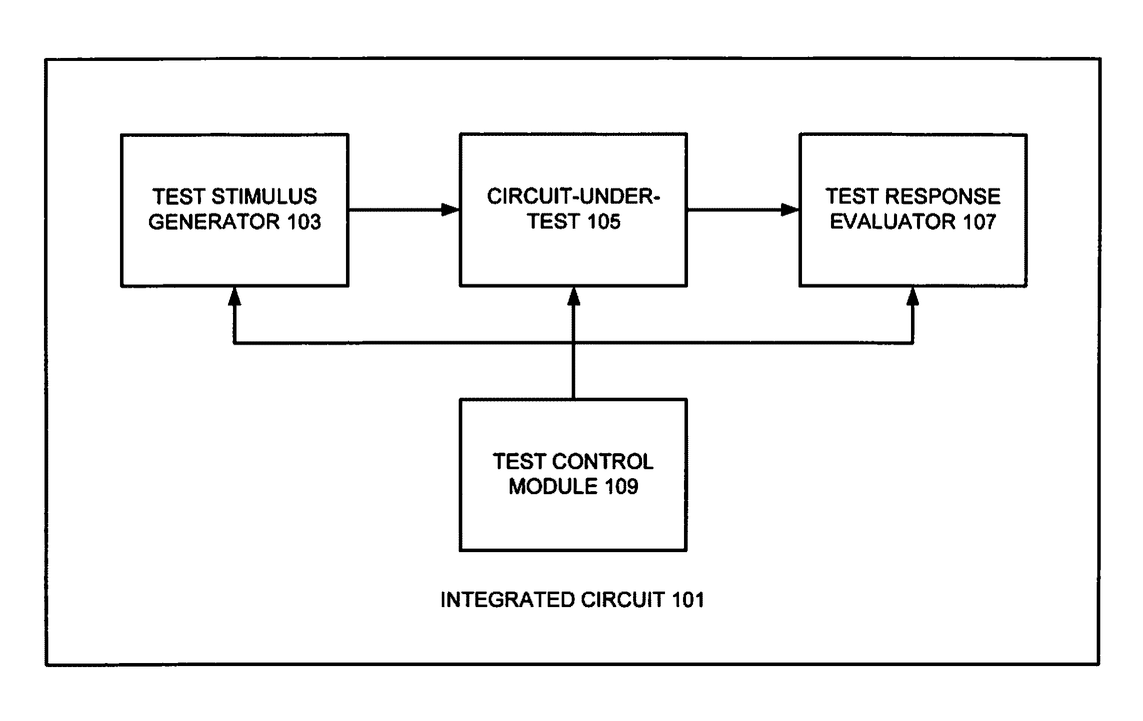
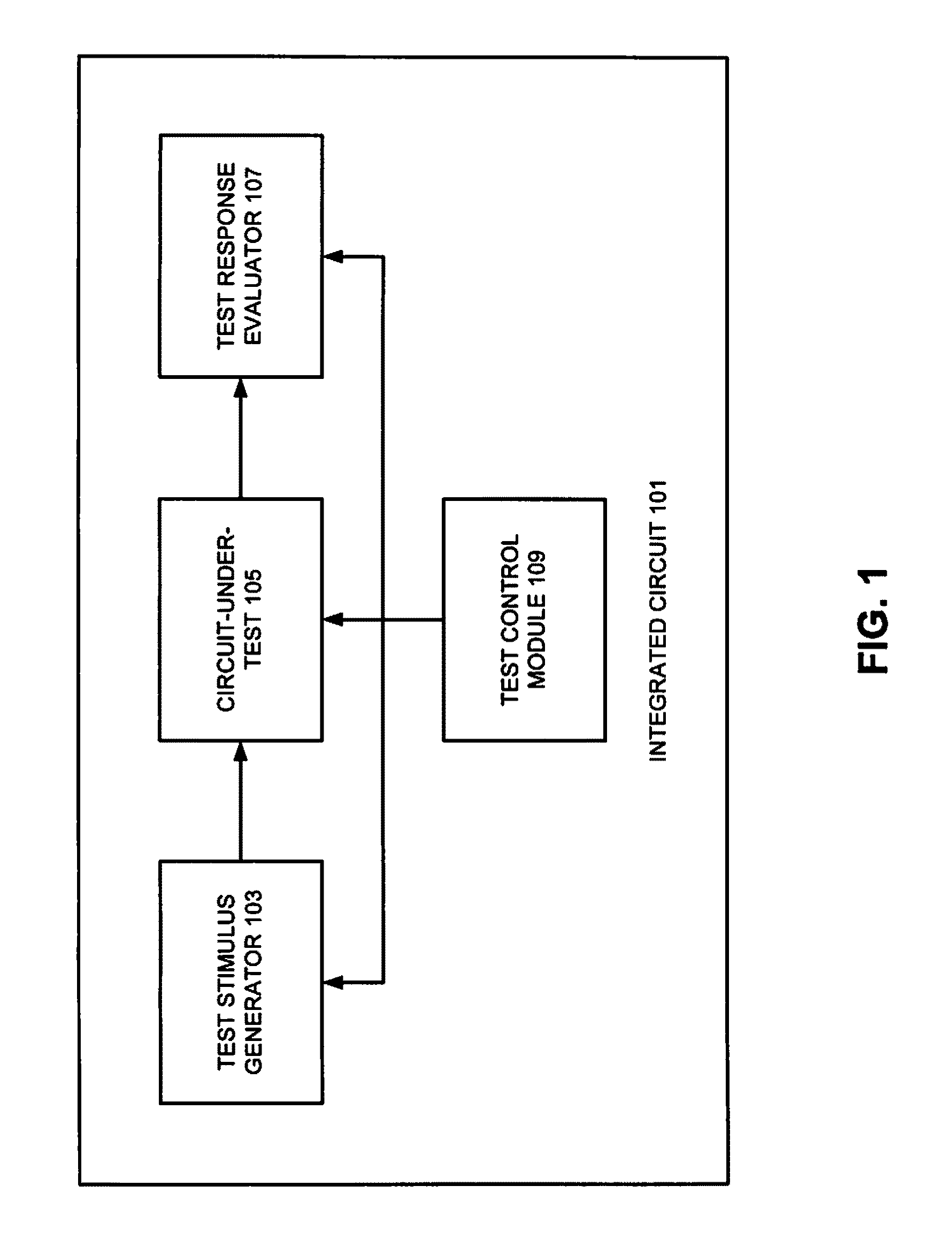
Built-In Self-Test System

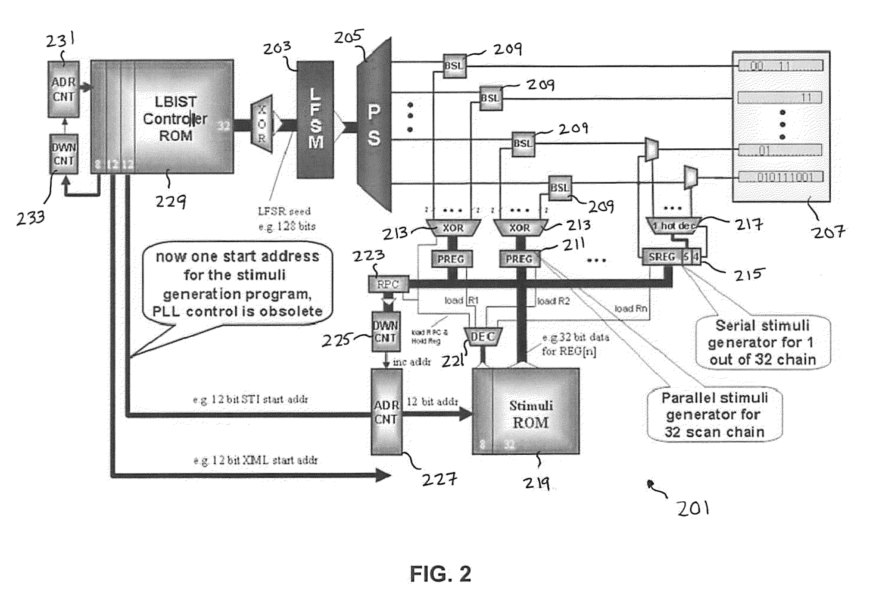
[0016]FIG. 2 shows an example of an Embedded Deterministic Test (EDT) configuration 201 that may be employed with various implementations of the invention. As seen in this figure, the EDT configuration 201 includes a linear feedback state machine (LFSM) 203 together with a phase shifter (PS) 205 connected to the linear feedback state machine 203. According to various embodiments of the invention, stimuli generation logic is placed between the outputs of the phase shifter 205 and the inputs of internal scan chains 207. This stimuli generation logic may include bit-setting logic (BSL) devices 209, one or more parallel data registers (PREG) 211 with corresponding XOR decompressors 213, and one or more serial data registers (SREG) 215 with corresponding 1-hot decoders 217. Further, with some implementations of the invention, the stimuli generation logic also may include a stimuli memory circuit device 219 (which may be, e.g., a read-only memory (ROM) device), a ...


PUM


Abstract

Techniques for storing and using compressed restrict values for selected scan chains and flip-flops, such that the states that need to be applied to those flip flops need not be solved by a linear equation system solver, such as a linear equation system solver provided by an automatic test pattern generation (ATPG) tool. Selected restrict values can then be injected into test patterns for those flip-flop combinations that need to be set in a certain shift cycle or those flip-flops that need to be initialized one after another (e.g., for serial settings in one scan chain).

Description

RELATED APPLICATIONS[0001]This application claims priority to U.S. Provisional Patent Application No. 61 / 119,016, entitled “Deterministic Logic Built-In Self-Test Stimuli Generation,” filed on Dec. 1, 2008, and naming Friedrich Hapke et al. as inventors, which application is incorporated entirely herein by reference.FIELD OF THE INVENTION[0002]The present invention is directed to the generation of deterministic test patterns for a built-in self-test of an integrated circuit device. Various embodiments of the invention may be particularly useful for providing values of a deterministic pattern to specific scan chains or to specific flip-flops in one or more scan chains of an embedded deterministic test system.BACKGROUND OF THE INVENTION[0003]As integrated circuits continue to develop, they continue to have higher device densities and clocking rates. As a result, it requires ever-increasing numbers of test vectors to properly test them, which in turn requires larger and larger amounts ...

Claims


Application Information

Patent Timeline
IPC IPC(8): G01R31/3177G06F11/25
CPCG01R31/318597G01R31/318558
Inventor HAPKE, FRIEDRICHWITTKE, MICHAELMEIER, REINHARD
Owner MENTOR GRAPHICS CORP
Why Eureka
Try Eureka