Construction machine

a construction machine and construction technology, applied in the direction of machines/engines, jet propulsion mounting, transportation and packaging, etc., can solve the problems of damage to the exhaust gas treatment device, the exhaust gas treatment member and the lik

Inactive Publication Date: 2010-11-04
NIHON KENKI CO LTD
View PDF12 Cites 61 Cited by
  • Summary
  • Abstract
  • Description
  • Claims
  • Application Information

AI Technical Summary

Benefits of technology

[0026]Therefore, the stopper member is able to restrain the exhaust gas treatment device from tending to undergo a large displacement in excess of an allowable range of the deformation of the vibration isolating member. It is possible to prevent such as causing damage to the vibration isolating member and interference of the exhaust gas treatment device with a surrounding member.

Problems solved by technology

However, since high-frequency vibrations of the engine are directly transmitted to the exhaust gas treatment device, there is a problem in that exhaust gas treatment members and the like constituting the exhaust gas treatment device can be damaged by these vibrations.

Method used


Image

  • Construction machine
  • Construction machine
  • Construction machine

Examples


first embodiment

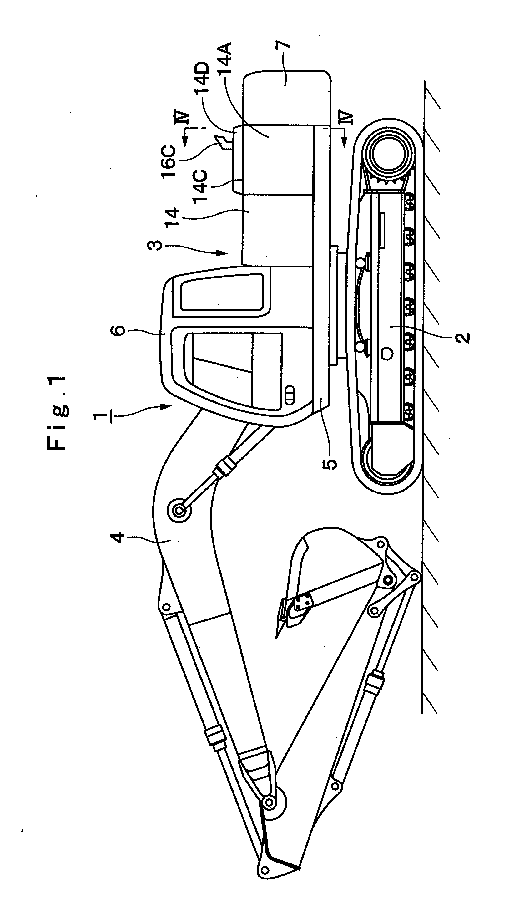
[0079]FIGS. 1 to 9 show the present invention. In FIG. 1, designated at 1 is a crawler type hydraulic excavator which is a typical example of construction machines, and this hydraulic excavator 1 is largely constituted by an automotive lower traveling structure 2, an upper revolving structure 3 which is swingably mounted on the lower traveling structure 2 and constitutes a vehicle body together with the lower traveling structure 2, and a working mechanism 4 liftably mounted on the front side of the upper revolving structure 3 to perform such as the operation of excavating earth and sand. The lower traveling structure 2 and the upper revolving structure 3 are specific examples of the vehicle body in accordance with the present invention.

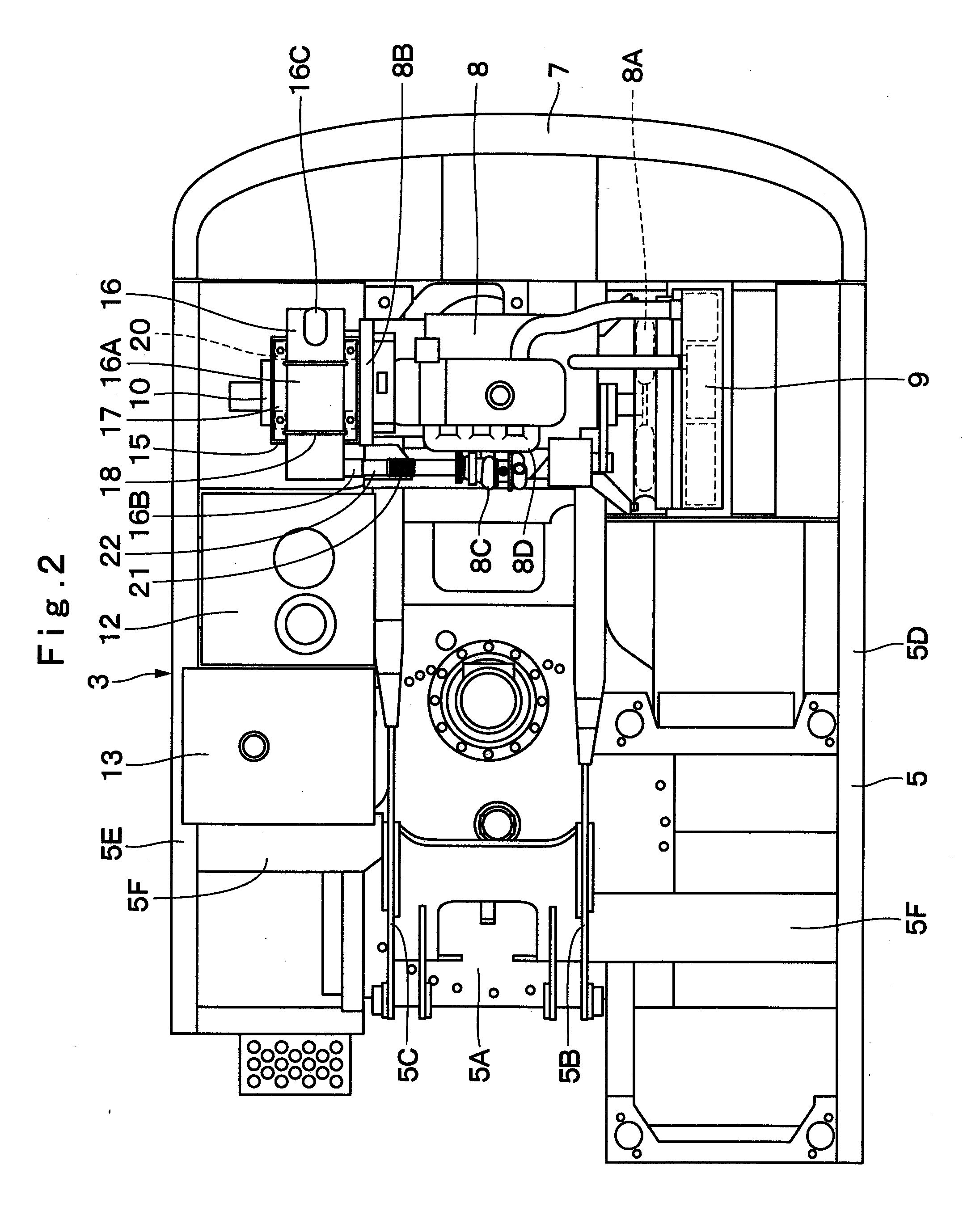
[0080]Here, the upper revolving structure 3 for constituting the hydraulic excavator 1 will be described in greater details.

[0081]Indicated at 5 is a revolving frame of the upper revolving structure 3, and the revolving frame 5 is formed as a supporti...

second embodiment

[0122]In FIG. 10, designated at 31 is a heat shielding cover in accordance with the second embodiment which is provided in such a manner as to cover the vibration isolating member 20. This heat shielding cover 31 is formed in the shape of a lidded cylinder by a cylinder portion 31A covering the periphery of the elastic deformation portion 20A of the vibration isolating member 20 and a lid portion 31B covering the upper side of the elastic deformation portion 20A. A passage hole 31C, into which the upper mounting screw portion 20B of the vibration isolating member 20 is inserted, is bored in the center of the lid portion 31B.

[0123]In consequence, as the heat shielding cover 31 is fitted over the vibration isolating member 20 from above while the upper mounting screw portion 20B is inserted into the passage hole 31C, the heat shielding cover 31 is able to cover the elastic deformation portion 20A formed of a rubber material or the like. In consequence, the heat shielding cover 31 is a...

third embodiment

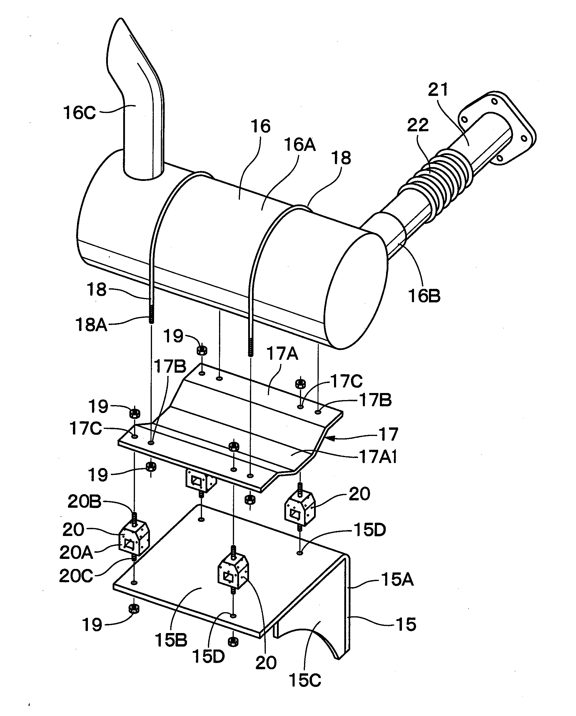
[0133]In FIGS. 11 and 12, designated at 41 is an exhaust gas treatment device in accordance with the third embodiment which is provided on the support member 15. This exhaust gas treatment device 41 is mounted on the supporting face portion 15B of the support member 15 by means of below-described mounting brackets 51 and 52 and the vibration isolating members 20. The exhaust gas treatment device 41 is largely constituted by an upstream cylinder 42, a downstream cylinder 43, an intermediate cylinder 44, an oxidation catalyst 46, and a particulate matter removing filter 47, and the like, which will be described hereinunder.

[0134]Namely, the exhaust gas treatment device 41 in accordance with the third embodiment is so constructed that three cylinders, namely, the upstream cylinder 42 located on the front side, the downstream cylinder 43 located on the rear side, and the intermediate cylinder 44 located therebetween, are flange-connected by use of bolts 45.

[0135]The upstream cylinder 42...


PUM


Abstract

An engine (8) is mounted to a vehicle body by means of vibration isolating mounts (8E), and a support member (15) is mounted to the engine (8). Vibration isolating members (20) are provided between this support member (15) and a mounting bracket (17) mounted to an exhaust gas treatment device (16). Accordingly, even in cases where the engine (8) has generated high-frequency vibrations, these vibrations can be damped by the vibration isolating mounts (8E) and the vibration isolating members (20). In consequence, treatment members constituting the exhaust gas treatment device (16) , such as a catalyst, a filter, and a sensor, can be protected from the vibrations of the engine (8). In addition, as the exhaust gas treatment device (16) is provided with the mounting bracket (17), the vibration isolating members (20) can be reliably mounted to the exhaust gas treatment device (16) by means of the mounting bracket (17).

Description

TECHNICAL FIELD[0001]The present invention relates to a construction machine such as a hydraulic excavator, and more particularly to a construction machine equipped with an exhaust gas treatment device for treating exhaust gas from an engine.BACKGROUND ART[0002]Generally, a hydraulic excavator as a typical example of construction machines is constituted by an automotive lower traveling structure, an upper revolving structure which is swingably mounted on the lower traveling structure, and a working mechanism liftably mounted on the front side of the upper revolving structure.[0003]The upper revolving structure is largely constituted by a revolving frame forming a supporting structure, a cab which is provided on the front side of the revolving frame and where an operator gets on board, an engine mounted on the rear side of the revolving frame, a hydraulic pump mounted on one longitudinal side of the engine, and an exhaust gas treatment device connected to an exhaust manifold of the e...

Claims


Application Information

Patent Timeline
Patent Type & Authority Applications(United States)
IPC IPC(8): F01N13/00F01N13/08F01N13/14
CPCB60K5/1208E02F9/00F01N2560/08F01N13/1816F01N13/1822E02F9/0866B60K13/04
Inventor KAMATA, HIROYUKIKOBAYASHI, TAKAHIROABE, TOSHIHIRO
Owner NIHON KENKI CO LTD
Why Eureka
Try Eureka