
Thermal Energy Storage Apparatus

a technology of thermal energy storage and apparatus, which is applied in the direction of lighting and heating apparatus, stationary tubular conduit assemblies, indirect heat exchangers, etc., can solve the problems of significant reduction of the heat conductivity of the apparatus, substantially slowing down the heat extraction process, and storing the thermal energy in the pcm (hereinafter melting cycle) also. to achieve the effect of rapid delivery of thermal energy

Inactive Publication Date: 2010-11-04
NUCLEAR RES CENT NEGEV
View PDF10 Cites 25 Cited by
  • Summary
  • Abstract
  • Description
  • Claims
  • Application Information

AI Technical Summary

Benefits of technology

[0015]It has now been found that it is possible to construct an energy storage apparatus capable of rapidly delivering thermal energy to / from a PCM contained in a heat conducting container comprising a thermal energy transfer element which provides a plurality of heat transfer paths between the central space of the heat conducting container and its inner wall. This new construction allow rapidly delivering thermal energy to / from the apparatus via a heat exchange fluid flowing in contact with the wall of the heat conducting container without requiring that the heat exchange fluid be circulated inside said energy storage apparatus.

Problems solved by technology

During the process of extracting the thermal energy from the PCM (herein after freezing cycle) the phase of the PCM adjacent to the inner surface of the container is the first to freeze (change from liquid state into solid state), which significantly reduces the heat conductivity of the apparatus, and as a result substantially slows down the heat extraction process.
Similarly, storing the thermal energy in the PCM (hereinafter melting cycle) is also substantially slow due to the low heat conductivity of the apparatus while the PCM is in its solid state.
The methods described above have not yet provided satisfactory solutions for efficiently storing thermal energy in a PCM based thermal energy storage apparatus and rapidly extracting the stored thermal energy therefrom.

Method used


Image

  • Thermal Energy Storage Apparatus
  • Thermal Energy Storage Apparatus
  • Thermal Energy Storage Apparatus

Examples


example 1

[0076]Table 1 lists the results obtained in a set of simulating experiments which were performed using a small test model. These experiments were carried out using a thermal energy storage apparatus constructed from a cylindrical tube having a diameter of 100 mm, made from steel in a thickness of 1 mm. The cylindrical tube was filled with a NaNO3 / KNO3 mixture having 250° C. fusion temperature, and it was tested without thermal energy transferring insert and with the various insert types demonstrated hereinabove. The thermal energy storage apparatus was installed in a container through which PazTherm22 heat transfer fluid was circulated. During the melting cycle the temperature of the heat transfer fluid was 260° C. which heated the PCM to about 250° C., and it was cooled to 240° C. for releasing the stored thermal energy in the freezing cycle.

TABLE 1Duration of stored energyInsert typeextraction[min]No insert128Brush insert32Elongated star insert40Spiral star insert40Mesh insert34

[0...

example 2

[0078]The following demonstration is a specific example for a thermal energy storage system of the invention that is designed to operate in 307° C. using NaNO3 as a PCM and VP1 as heat transfer fluid. This system is designed for storing about 1 MWthh within 4 hours (i.e., power of 250 kWth) and for delivering the same in about 2 hours (i.e., power of 500 kWth).

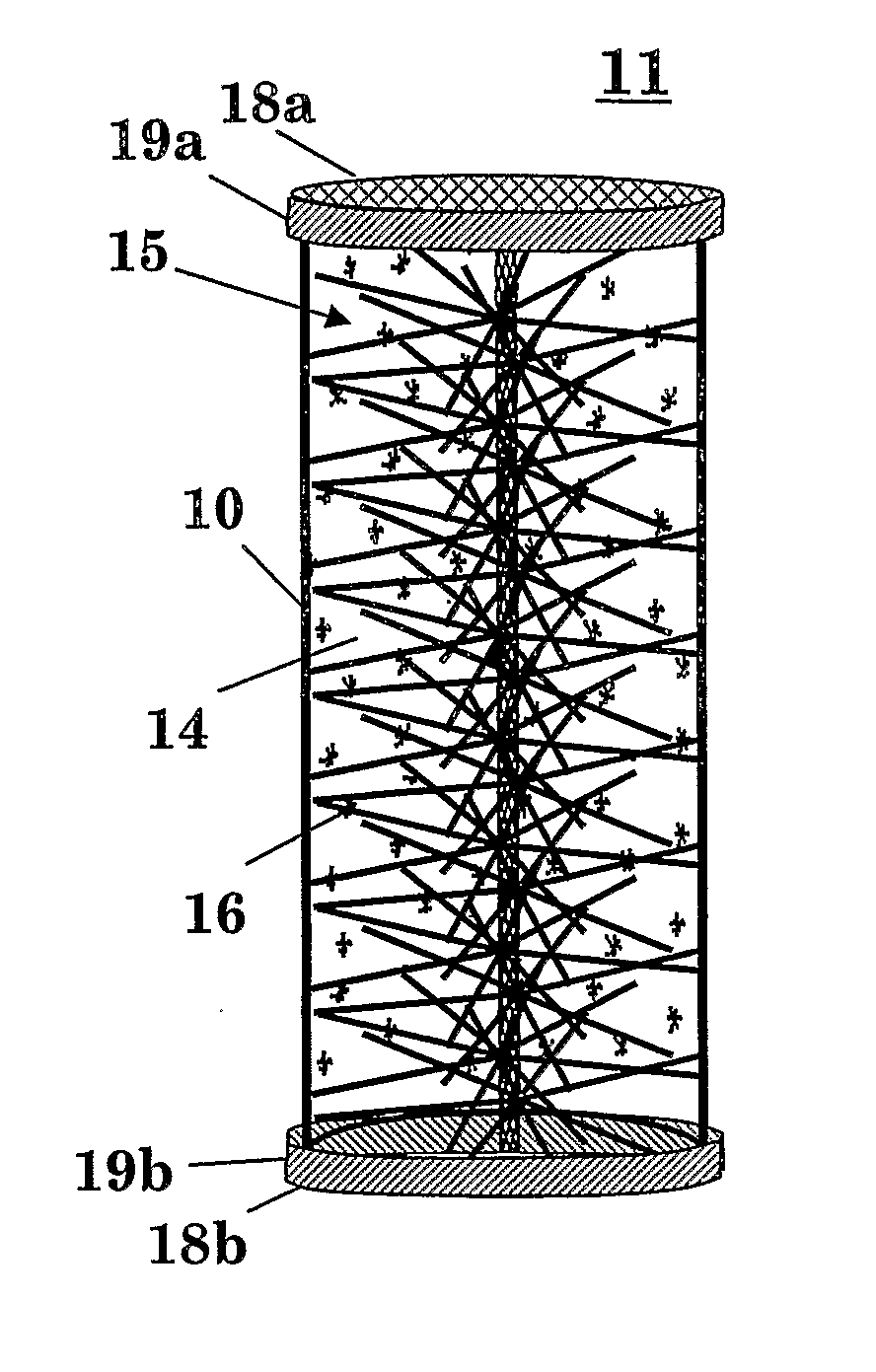
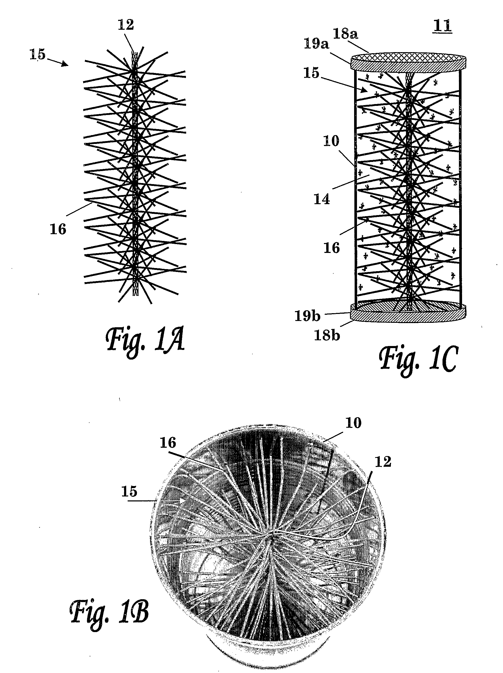
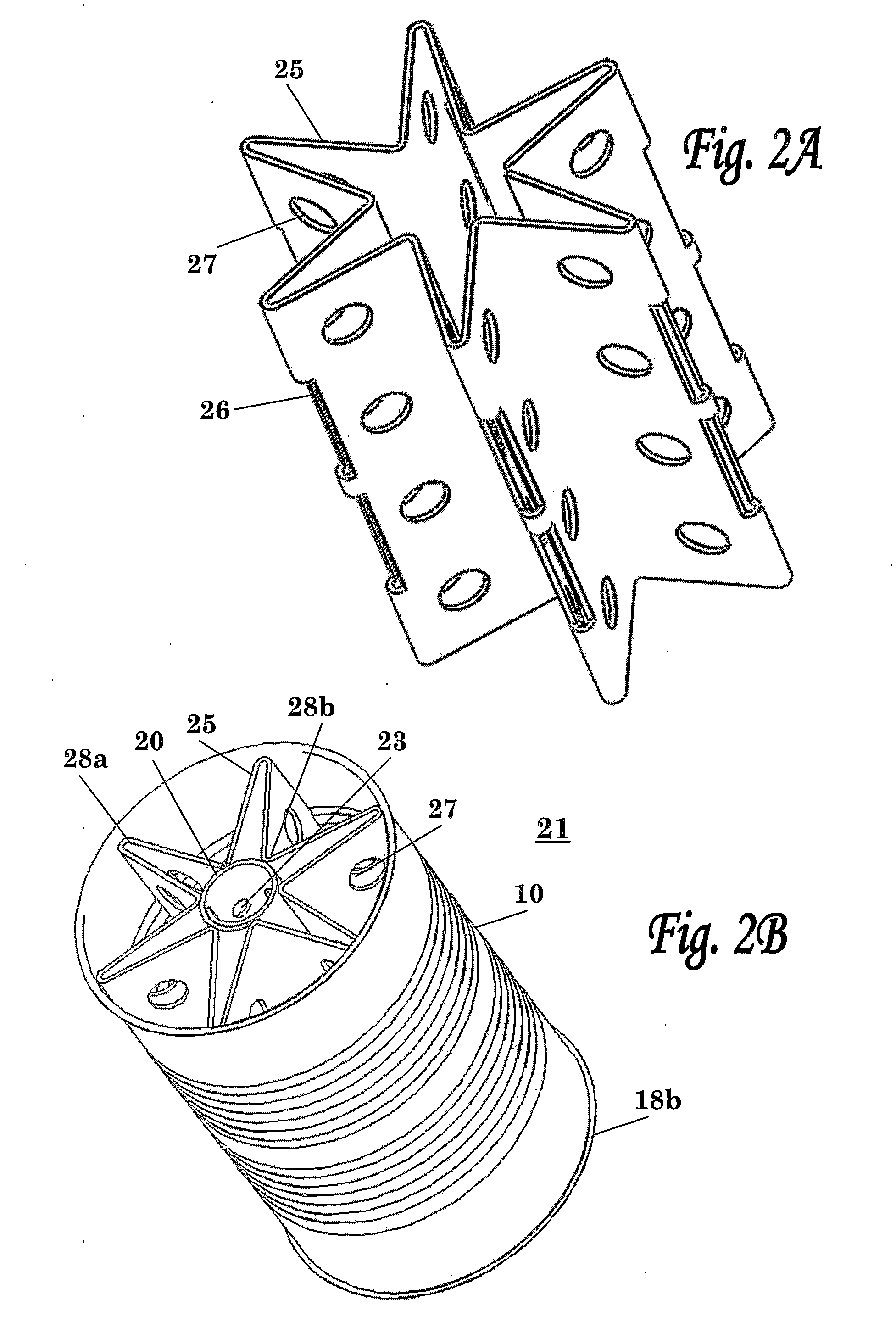
[0079]In this example the thermal energy storage apparatus is implemented utilizing an elongated heat conducting tube containing the PCM and an elongated aluminum star insert. The elongated star insert consists of six apex points and it is of the same length as the heat conducting tube.

[0080]Table 2 provides geometric parameters of the exemplified thermal energy storage apparatus:

TABLE 2ParameterSize / QuantityNotesTube inner diameter10 cmTube length400 cmmade of Carbide SteelTube volume31.416 literNumber of tubes310Total volume9739 literLatent heat per0.116 kWthh / literliterFill coefficient -0.9PCM filling factorTotal energy sto...

example 3

[0081]FIG. 7 graphically illustrates the results obtained in a computerized simulation in which the heat transfer of the thermal energy storage apparatus of the invention was tested, and wherein the configuration of the simulated heat transfer apparatus was as follows: the heat conducting tube of the apparatus is a steel tube having a 100 mm inner diameter and comprising an elongated star insert made of pure Aluminum (e.g., Aluminum 1100) having 6 apex points and 1 mm thickness. In the simulation SylTherm800 oil was used as a heat transfer fluid and the temperature difference between the heat transfer fluid and the melted PCM salt (NaNO3) was 10° C.

[0082]FIG. 7 shows the results of the computerized simulation, wherein the curves shown illustrates the rate of solidification over time which represents the power extracted from the tube assembly. Curve 60 illustrates the results obtained in a simulation of the heat transfer apparatus containing the elongated star insert, and curve 61 il...


PUM


Abstract

The present invention is primarily directed to a thermal energy storage apparatus for delivering thermal energy to or from a PCM, comprising an elongated heat conducting container (10) having an insertable thermal energy transfer element (15) placed therein, wherein said thermal energy transfer element comprises a plurality of heat transfer paths in the form of transversely disposed flexible heat conducting members (16), at least a portion of which are in contact with the inner wall of said container (10). The invention is also directed to a system using the thermal energy storage apparatus of the invention.

Description

FIELD OF THE INVENTION[0001]The present invention relates to the field of thermal energy storage. More particularly, the invention relates to a phase change materials (PCM) based method and apparatus, with improved thermal conductivity for storing and delivering thermal energy.BACKGROUND OF THE INVENTION[0002]Thermal Energy Storage (TES) technologies provide efficient and cost effective solutions in various heat process industries (e.g., solar heat systems). Common TES technologies that are used nowadays might be classified to either sensible heat or fusion heat storage. The present invention aims to provide an efficient fusion heat storage apparatus based on a phase change material.[0003]Phase change thermal energy storage is based on the large heat of fusion of some Phase Change Materials (PCM, e.g., paraffin waxes, inorganic salts). Typically, in this type of energy storage applications the phase of the PCM changes from solid state into liquid state during storage of thermal ener...

Claims


Application Information

Patent Timeline
Patent Type & Authority Applications(United States)
IPC IPC(8): F28D20/02F28D15/00F28F7/00
CPCF28D7/1607F28D20/02Y02E60/145F28F1/40F28F13/06F28D2020/0013Y02E60/14
Inventor SAGIE, DANASSIS, ELI
Owner NUCLEAR RES CENT NEGEV
Features
  • Generate Ideas
  • Intellectual Property
  • Life Sciences
  • Materials
  • Tech Scout
  • Unparalleled Data Quality
  • Higher Quality Content
  • 60% Fewer Hallucinations
Learn More