
Drilling in stretched substrates

Inactive Publication Date: 2010-11-04
ARADIGM
View PDF5 Cites 62 Cited by
  • Summary
  • Abstract
  • Description
  • Claims
  • Application Information

AI Technical Summary

Benefits of technology

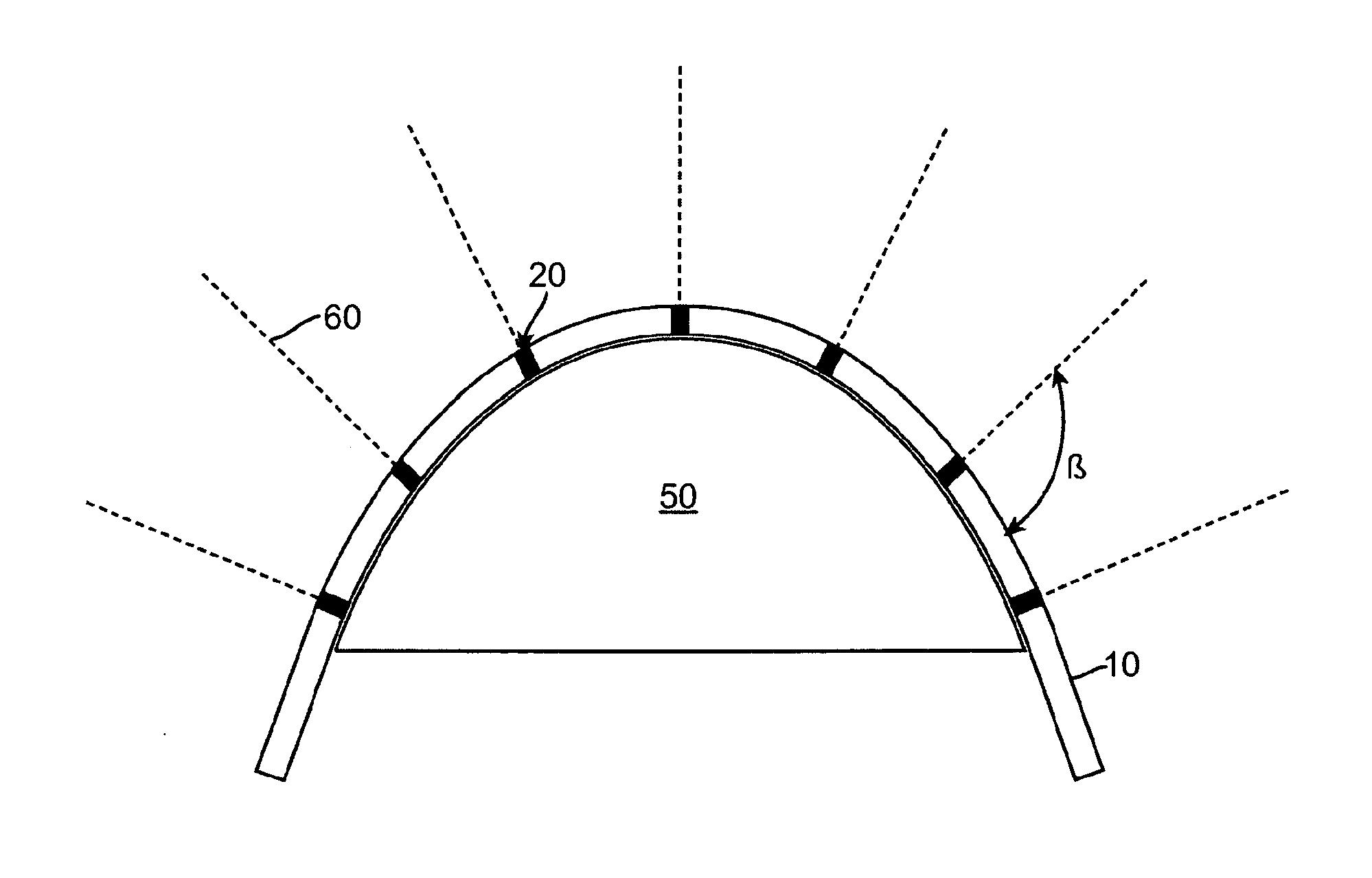
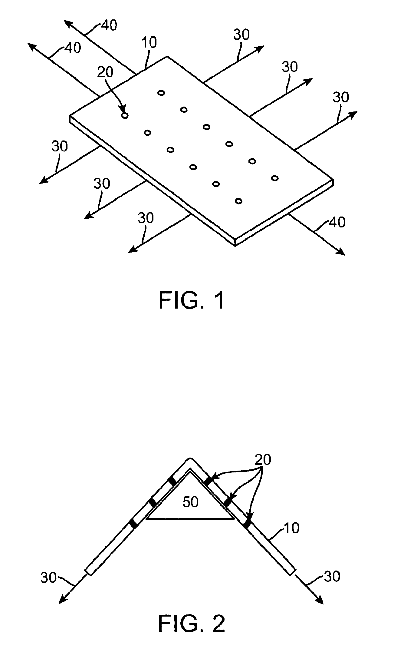
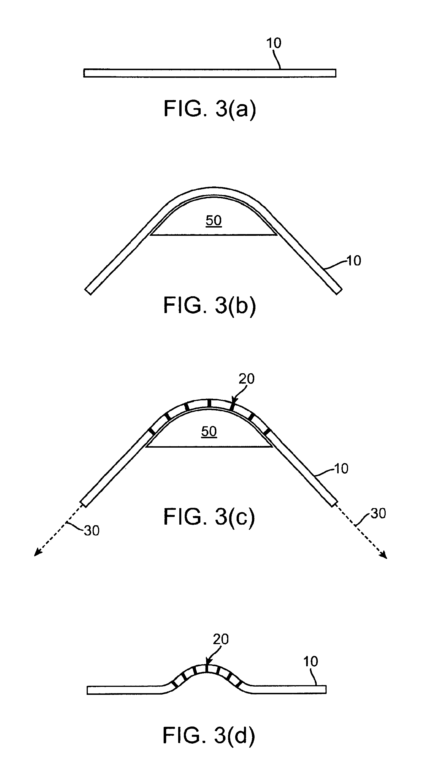
[0017]In view of the above noted disadvantages, the present invention relates to generating nozzles (i.e., holes) in a flexible or deformable membrane or substrate that retain the above-noted advantages while minimizing the effect of nozzle stretching. This technology will herein be referred to as Drill After Stretch (DAS) or Drill After Deform (DAD) technology. Instead of drilling nozzles (e.g., using LASER technologies) into a typical flat membrane or substrate, DAS / DAD technology seeks to pre-stretch and / or pre-deform the membrane or substrate to the final operating shape or near final operating shape, prior to or during drilling. The present invention also relates to generation of aerosol from substrates made using DAS / DAD technology which aerosols are used to treat patients. In this way, the hole size during aerosol generation can be made smaller and can be controlled within a narrower range as compared to not using DAS.
[0019]In addition, it has heretofore been unknown to use jet impingement technology in combination with the Drill After Stretch (DAS) or Drill After Deform (DAD) technology described herein. Thus, combining jet impingement technology with Drill After Stretch (DAS) or Drill After Deform (DAD) technology as described herein may reduce the above noted disadvantages for example by: (1) generating a low velocity aerosol to permit wider device design latitude, (2) allow the use of larger nozzles, and / or (3) provide a desirable aerosol by pressurizing a fluid through the nozzles at lower pressures than previously known.
[0024]The present invention can also provide an apparatus and method for drilling nozzles in substrates wherein the nozzles are oriented in such a way as to provide impinging jets upon moving fluid through the nozzles which can more easily facilitate the formation of an aerosol.

Problems solved by technology

However, the above noted documents fail to disclose at least generation of an aerosol from the holes formed in the substrates.
While this ballooning may be into an air flow and as such be advantageous from an aerodynamic point of view, the porous membrane stretches substantially during this process, which can result in enlarged nozzle holes that may result in several drawbacks.
However, one drawback is that stretched holes result in larger aerosol particles.
This can result in a requirement of using a heater in the device to evaporate the particles to reduce size.
Simply drilling smaller holes in the membrane prior to stretching during use can be limited by the optical properties of LASER hole drilling, coupled with the fact these smaller drilled holes can themselves stretch to a larger size during use.
This can potentially lead to system variability.
Likewise, jetting from small hole sizes requires substantial energy that can result in an aerosol with appreciable velocity.
Such a high speed aerosol can require careful airway design to effectively deliver aerosol to the patient and can limit device design options.
However, the above noted document utilizes a complicated nozzle assembly, which can result in a cumbersome overall device construction and design, and which may lead to nozzle clogging.

Method used


Image

  • Drilling in stretched substrates
  • Drilling in stretched substrates
  • Drilling in stretched substrates

Examples


Embodiment Construction

[0035]The particulars shown herein are by way of example and for purposes of illustrative discussion of the embodiments of the present invention only and are presented in the cause of providing what is believed to be the most useful and readily understood description of the principles and conceptual aspects of the present invention. In this regard, no attempt is made to show structural details of the present invention in more detail than is necessary for the fundamental understanding of the present invention, the description taken with the drawings making apparent to those skilled in the art how the several forms of the present invention may be embodied in practice.

[0036]It is noted that the foregoing examples have been provided merely for the purpose of explanation and are in no way to be construed as limiting of the present invention. While the present invention has been described with reference to a preferred embodiment, it is understood that the words which have been used herein...


PUM

PropertyMeasurementUnit
Angleaaaaaaaaaa
Angleaaaaaaaaaa
Angleaaaaaaaaaa

Abstract

The present invention provides a method and apparatus for drilling a plurality of holes in a stretched substrate in at least two directions not in the same plane, including providing a substrate in a substrate holder, stretching the substrate in at least one direction to a stretched configuration, and drilling at least one hole in the substrate while in a stretched configuration. The present invention further provides methods and apparatus for drilling impinging jet nozzles in stretched or pre-stretched substrates.

Description

CROSS-REFERENCE[0001]This application is a 371 National Phase of International Application No. PCT / US2008 / 011199, filed Sep. 26, 2008, which claims priority to U.S. Provisional Application Ser. No. 60 / 975,221 filed Sep. 26, 2007, U.S. Provisional Application Ser. No. 60 / 982,759 filed Oct. 26, 2007, and U.S. Provisional Application Ser. No. 61 / 023,906 filed Jan. 28, 2008, all of which are incorporated herein by reference in their entirety noting that the current application controls to the extent there is any contradiction with any earlier application and to which applications we claim priority under 35 USC §120.FIELD OF THE INVENTION[0002]This invention is directed to methods and apparatus for drilling holes in stretched or pre-stretched substrates to create nozzles, and methods and apparatus for drilling holes to create impinging jet nozzles, and combinations thereof.BACKGROUND OF THE INVENTION[0003]It is desirable in different areas of technology to make use of a thin sheet of mat...

Claims


Application Information

Patent Timeline
IPC IPC(8): B05B1/14B05B17/00B23K26/38B05B1/26
CPCB23K26/421B23K26/383B23K26/385B23K26/388B23K26/4005Y10T408/29B23K26/4015B23K26/402B23K26/4065B23K26/4085B23K26/401B23K26/40B23K26/384B23K26/60B23K26/389B23K2103/02B23K2103/05B23K2103/08B23K2103/12B23K2103/14B23K2103/16B23K2103/26B23K2103/42B23K2103/50
Inventor SMITH, ROGER EARL
Owner ARADIGM
Learn More