Flexural vibration piece

a technology of vibration piece and flexural body, which is applied in the direction of piezoelectric/electrostrictive/magnetostrictive devices, piezoelectric/electrostriction/magnetostriction machines, device details, etc., can solve the problem of deterioration in performance, such as an increase or decrease in ci value or q value, and the rigidity of the vibration arm is significantly deteriorated. problem, to achieve the effect of sufficiently

Inactive Publication Date: 2010-11-04
SEIKO EPSON CORP
View PDF9 Cites 20 Cited by
  • Summary
  • Abstract
  • Description
  • Claims
  • Application Information

AI Technical Summary

Benefits of technology

[0018]An advantage of some aspects of the invention is that it provides a flexural vibration piece, in which first and second grooves in a longitudinal direction are formed at first and second main faces arranged opposite each other of a vibration arm extending from a base portion, and the first and second grooves are arranged to be shifted to the opposite sides between the first and second main faces in a width direction with respect to a longitudinal center line of the vibration arm, and which is capable of eliminating or suppressing a vibration component in a vertical direction with respect to the first and second main faces at the time of flexural vibration of the vibration arm to eliminate or reduce vibration leakage, thereby improving a Q value, improving a CI value, achieving high performance, and realizing reduction in size and thickness.

Problems solved by technology

In the flexural vibration mode piezoelectric vibration piece, if loss of vibration energy occurs at the time of flexural vibration of the vibration arm, deterioration in performance, such as an increase in the CI value or a decrease in the Q value, may occur.
However, as described in Japanese Utility Model Application No. 63-110151, if a through hole is formed in the vibration arm, undesirably, rigidity of the vibration arm is significantly deteriorated.
As described in the related art, in the piezoelectric vibration piece in which grooves are formed at the front and rear surface of the vibration arm on the center line, it is difficult to sufficiently prevent or suppress the decrease in the Q value due to the thermoelastic effect.
In the flexural vibration piece, the reduction in size causes a decrease in the Q value, such that the decrease in the Q value due to vibration leakage interferes with reduction in size and thickness of the vibration piece.

Method used


Image

  • Flexural vibration piece
  • Flexural vibration piece
  • Flexural vibration piece

Examples


first embodiment

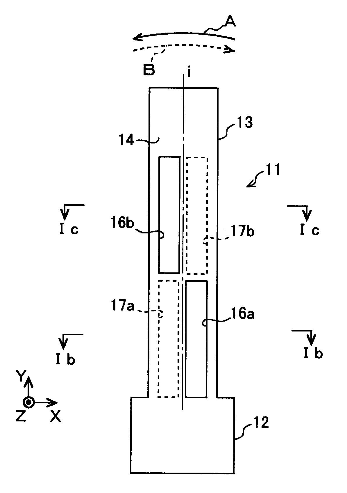
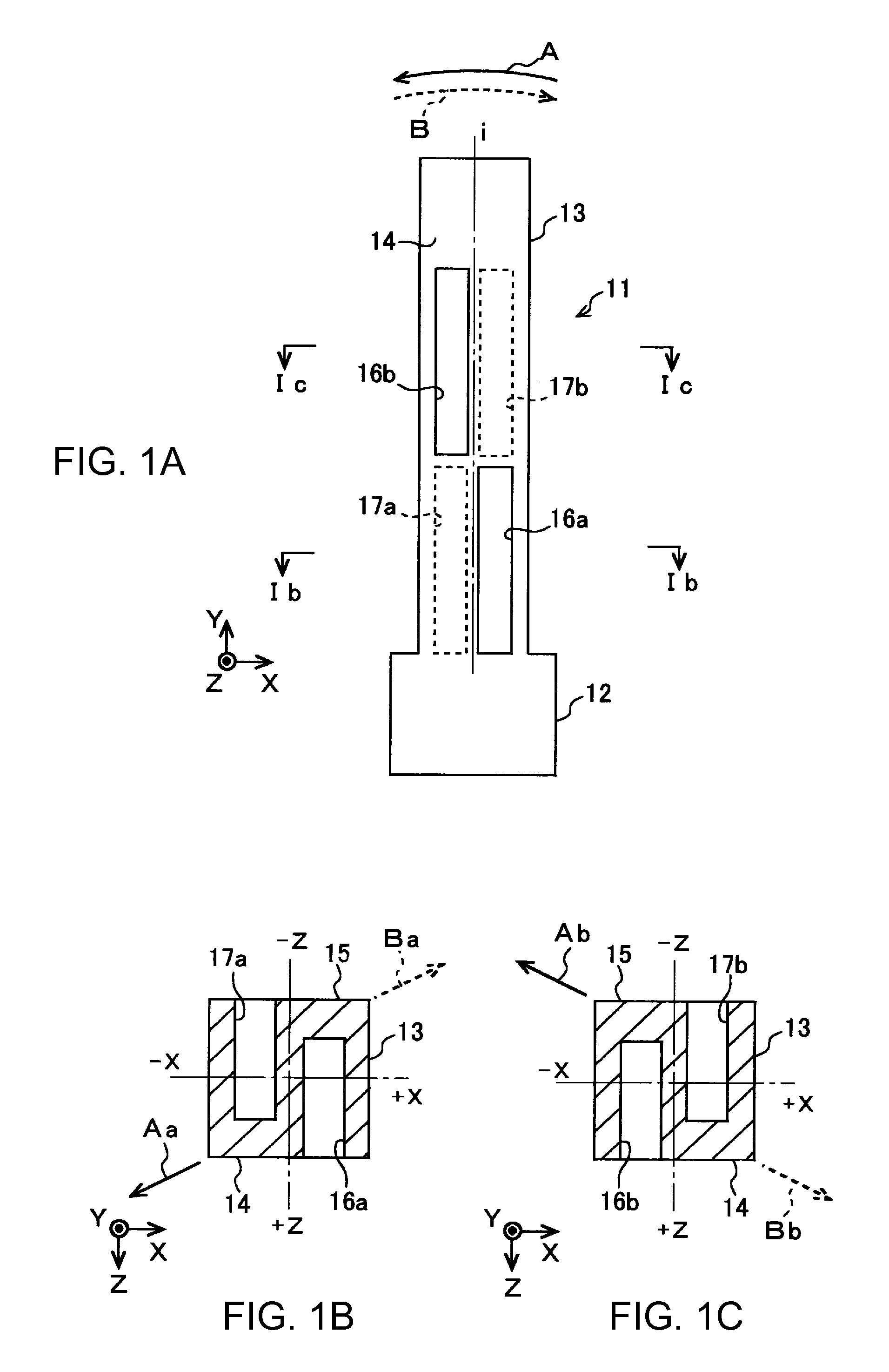
[0037]FIG. 1A schematically shows a flexural vibration piece according to the invention. A flexural vibration piece 11 of this embodiment has one vibration arm 13 which extends in parallel from a base portion 12. A first groove and a second groove are formed at front and rear main faces 14 and 15 of the vibration arm 13 so as to extend in the longitudinal direction from a connection portion to the base portion. The piezoelectric vibration piece 11 is formed integrally of quartz. Of the quartz crystal axes, the electrical axis X is aligned in the width direction of the vibration arm, the mechanical axis Y is aligned in the longitudinal direction of the vibration arm, and the optical axis Z is aligned in the thickness direction of the vibration piece. In another embodiment, a piezoelectric material other than quartz or a semiconductor material, such as silicon, may be used.

[0038]The first groove at the front-side main face 14 is divided into two first groove portions 16a and 16b which...

fifth embodiment

[0056]FIG. 5A schematically shows a piezoelectric vibration piece according to the invention. A flexural vibration piece 31 of this embodiment is a tuning-fork type flexural vibration piece which has a pair of vibration arms 33 and 34 extending in parallel from a base portion 32.

[0057]A first groove and a second groove are formed at front and rear main faces 35 and 36 of the vibration arm 33 so as to extend in the longitudinal direction from connection portions to the base portion. The first groove at the front-side main face 35 is divided into two first groove portions 37a and 37b which have the same width, length, and depth in the longitudinal direction of the vibration arm 13. The first groove portions are arranged to be alternately shifted on both sides in the width direction with respect to the longitudinal center line i of the vibration arm 33 in the longitudinal direction. Similarly, the second groove at the rear-side main face 36 is divided into two second groove portions 38...

seventh embodiment

[0076]Similarly to the seventh embodiment, first and second grooves are respectively formed at the first and second main faces of the vibration arms 73 to 75 so as to extend in the longitudinal direction from connection portions to the base portion. The first and second grooves of the vibration arm 73 on the left side of the drawing are respectively divided into two first groove portions 82a and 82b and second groove portions 83a and 83b which have the same width, length, and depth in the longitudinal direction. The first groove portions 82a and 82b and the second groove portions 83a and 83b are respectively arranged to be alternately shifted on both sides with respect to longitudinal center lines i1 and i2 of the vibration arm 73 in the longitudinal direction and on the opposite sides with respect to the longitudinal center lines i1 and i2.

[0077]Similarly, the first and second grooves of the vibration arm 74 at the center of the drawing are respectively divided into two first groov...


PUM


Abstract

A flexural vibration piece includes: a base portion; and a vibration arm extending from the base portion, wherein the vibration arm has first and second main faces which are arranged to be opposite each other, the first and second main faces respectively have first and second grooves which are formed in the longitudinal direction of the vibration arm, the first groove has a plurality of first groove portions which are divided in the longitudinal direction of the vibration arm and arranged to be alternately shifted on both sides with respect to the longitudinal center line of the vibration arm in the longitudinal direction, the second groove has a plurality of second groove portions which are divided in the longitudinal direction of the vibration arm, and arranged to be alternately shifted on both sides with respect to the longitudinal center line of the vibration arm in the longitudinal direction and on an opposite side to the first groove portions with respect to the longitudinal center line, and a predetermined voltage is applied to first excitation electrodes provided at the first groove and the second groove and second excitation electrodes provided on both side faces of the vibration arm, such that the vibration arm flexural-vibrates in the in-plane direction of the first or second main face.

Description

BACKGROUND[0001]1. Technical Field[0002]The present invention relates to a flexural vibration piece that is used for various piezoelectric devices, such as vibrators or resonators, oscillators, gyroscopes, and various sensors, and other electronic devices, and vibrates in a flexural vibration mode.[0003]2. Related Art[0004]A flexural vibration mode piezoelectric vibration piece, such as a tuning-fork type piezoelectric vibration piece, generally has a structure in which grooves are formed at the front surface and / or the rear surface of the vibration arm in the longitudinal direction, and excitation electrodes are formed at the inner surfaces of the grooves (for example, see International Publication No. WO00 / 44092). Such a vibration arm is configured such that an electric field is generated between an excitation electrode at the side surface of the vibration arm and the excitation electrodes in the grooves so as to be widely distributed over the cross-section of the vibration arm, t...

Claims


Application Information

Patent Timeline
Patent Type & Authority Applications(United States)
IPC IPC(8): H01L41/02
CPCH03H9/215H03H9/19
Inventor YAMAZAKI, TAKASHIFURUHATA, MAKOTO
Owner SEIKO EPSON CORP
Why Eureka
Try Eureka