Detection and ranging methods and systems

a range and detection method technology, applied in the field of detection and ranging methods and systems, can solve the problems of system slowness and limitations of some applications, and achieve the effects of low cost, low sample rate, and virtually increased sample rate of ad

Active Publication Date: 2010-11-04
LEDDARTECH INC
View PDF16 Cites 69 Cited by
  • Summary
  • Abstract
  • Description
  • Claims
  • Application Information

AI Technical Summary

Benefits of technology

[0017]According to another broad aspect of the present invention, there is provided a powered lighting system for acquiring a detected light optical signal and generating an accumulated digital trace. The powered lighting system comprising at least one light source for illumination of a field of view and emitting a pulse in the field of view; an illumination driver for driving the light source; an optical detector for detecting a reflection signal of a reflection of the pulse; an analog-to-digital converter (ADC) with a sample rate of F Hz and B bits of resolution for acquiring j points for the detected reflection signal by acquiring one of the j points at each 1/F second thereby converting the optical reflection signal into a digital signal waveform of j points; a buffer for storing the digital signal waveform; a processor for controlling the illumination driver and the optical detector; sending information for storage in the buffer, wherein a length of the buffer is at least j×P and a number of...

Problems solved by technology

It can be set high to avoid false alarms but the system will not detect objects that return weak signal reflection.
Some techniques help to detect a certain number of echoes an...

Method used


Image

  • Detection and ranging methods and systems
  • Detection and ranging methods and systems
  • Detection and ranging methods and systems

Examples


Embodiment Construction

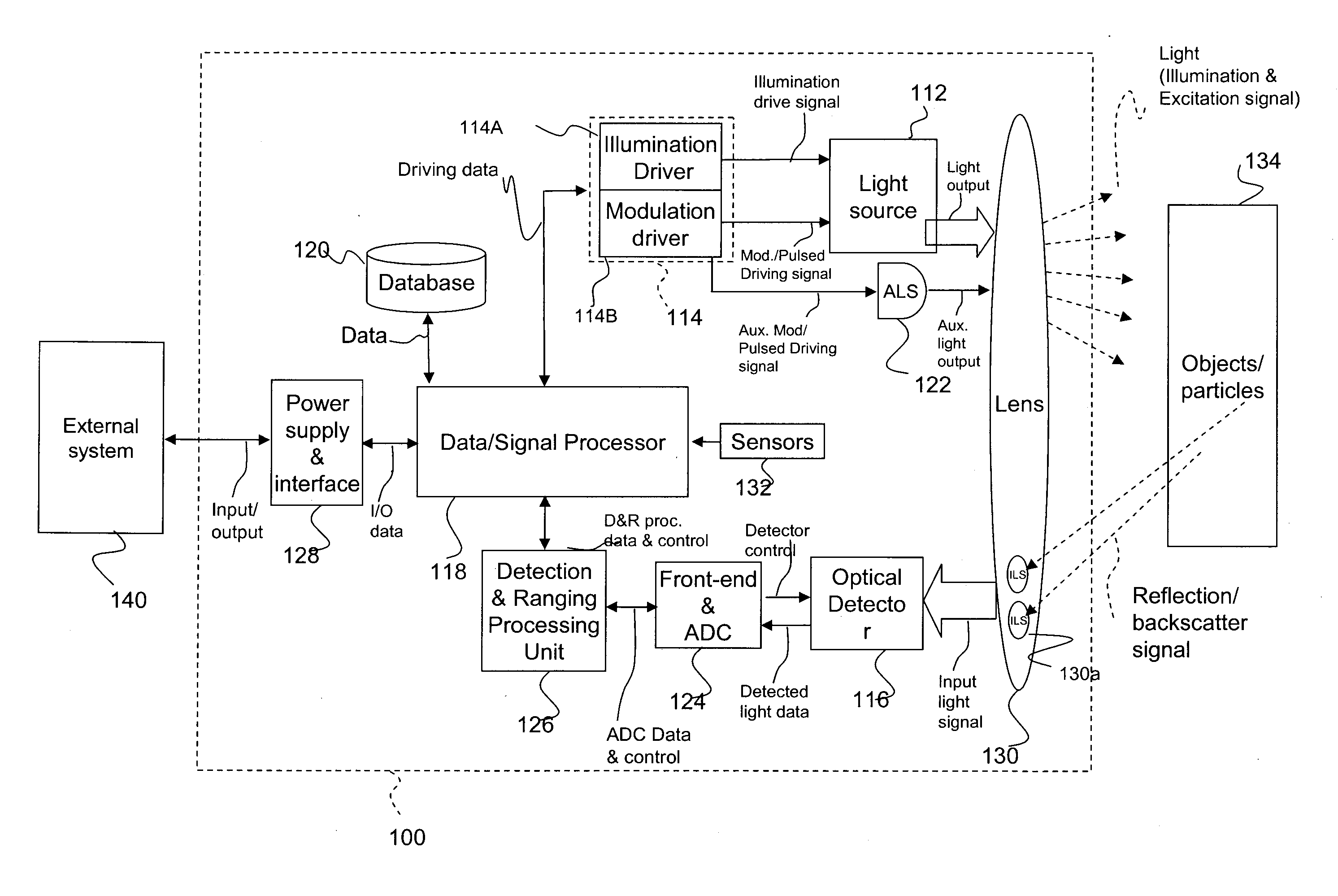
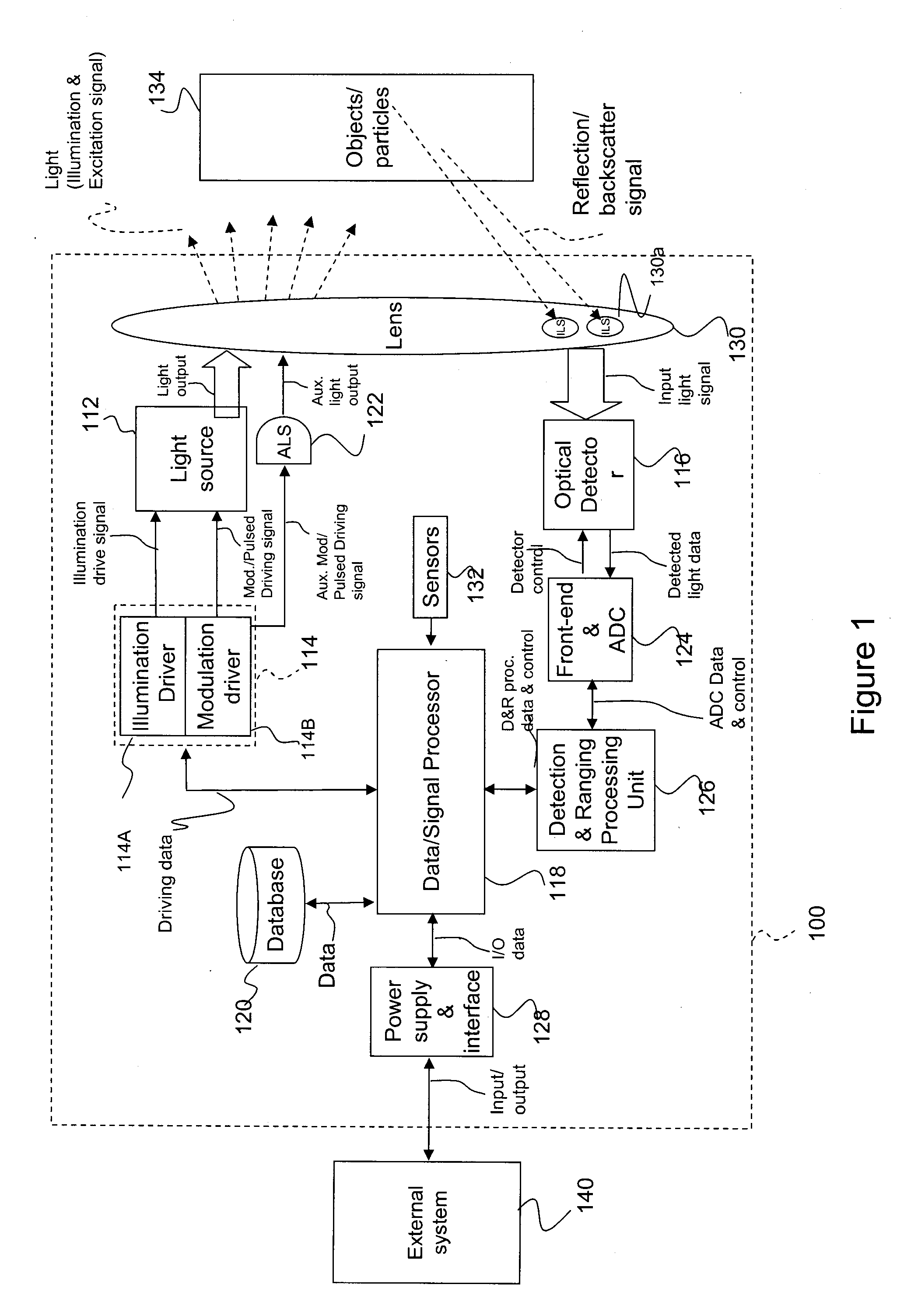
[0038]FIG. 1 is a block diagram illustrating an embodiment of a lighting system equipped with the present system. The lighting system 100 has a visible-light source 112. The visible-light source 12 has, as a first purpose, the emission of visible light for illumination or visual communication of information, like signaling, for human vision. The primary purpose of emitting light is controlled according to specific criteria like optical power, field of view and light color, to meet requirements defined through a number of regulations. In the preferred embodiment, the visible-light source 112 has one or more solid-state lighting devices, LEDs or OLEDs for instance.

[0039]The visible-light source 112 is connected to a source controller 114, so as to be driven into producing visible light. In addition to emitting light, the system 100 performs detection of objects and particles (vehicles, passengers, pedestrians, airborne particles, gases and liquids) when these objects are part of the e...


PUM


Abstract

There is provided a system and a method for acquiring a detected light optical signal and generating an accumulated digital trace The method comprises providing a light source for illumination of a field of view, an optical detector, an analog-to-digital converter (ADC), emitting one pulse from the light source in the field of view, detecting a reflection signal of the pulse by the optical detector, acquiring j points for the detected reflection signal by the ADC, storing, in a buffer, the digital signal waveform of j points, introducing a phase shift of 2pi/P, repeating, P times, the steps of emitting, detecting, acquiring, storing and introducing, to store, in the buffer, an interleaved waveform of P×j points, accumulating M traces of interleaved P×j points for a total of N=M×P acquisition sets, N being a total number of pulses emitted, creating one combined trace of the reflected signal of j×P points by adding each point of the M traces Additionally, the combined trace can be compared to a detected reference reflection signal of the pulse to determine a distance traveled by the pulse

Description

CROSS-REFERENCE TO RELATED APPLICATIONS[0001]This application claims priority of U.S. provisional patent applications Nos. 61 / 015,738; 61 / 015,867 and 61 / 042,424 filed on Dec. 21, 2007; Dec. 21, 2007 and Apr. 4, 2008, respectively, by Applicant.TECHNICAL FIELD[0002]The invention relates to methods and systems for improving the measurement of light transit time reflected by different types of objects in detection and ranging methods and systems.BACKGROUND OF THE ART[0003]Several methods are used to measure the distance between an apparatus and an object. Optical range-finding systems frequently rely on the time-of-flight principle and determine the distance between the apparatus and the object by measuring the time a short pulse of light emitted from the apparatus takes to reach an object and be reflected to a photo-detection circuit. Conventional optical rangefinders use a counter initiated at the starting pulse and then stopped when the receiver circuit detects the pulse echo of a v...

Claims


Application Information

Patent Timeline
IPC IPC(8): G01S17/02G01S7/4861G01S7/4865G01S17/10
CPCG01S7/003G01S7/487G01S7/4865G01S7/4861G01S17/10
Inventor MIMEAULT, YVAN
Owner LEDDARTECH INC
Why Eureka
Try Eureka