Lens barrel and lens support structure

a technology of lens support and barrel, which is applied in the field of lens support structure, can solve the problems of the quantity of lenses, and achieve the effects of reducing the magnification ratio, reducing the size of the lens barrel, and widening the angl

Active Publication Date: 2010-11-04
PANASONIC CORP
View PDF10 Cites 34 Cited by
  • Summary
  • Abstract
  • Description
  • Claims
  • Application Information

AI Technical Summary

Benefits of technology

[0010]On the other hand, if the first lens group has a negative refractive power (in the case of an imaging optical system that is called a negative lead type), it is more difficult to attain a high magnification ratio than with a positive lead type, but there are fewer lenses, which is advantageous in terms of making the lens barrel smaller, and is also suited to achieving a wider angle.
[0011]Thus, when the first lens group has a negative refractive power, it is easier to obtain a lens barrel that is compact and has a wider angle.
[0012]Nevertheless, w

Problems solved by technology

For instance, if the first lens group has a positive refractive power (in the case of an imaging optical system that is called a positive lead type), it

Method used


Image

  • Lens barrel and lens support structure
  • Lens barrel and lens support structure
  • Lens barrel and lens support structure

Examples


Embodiment Construction

[0084]Overview of Digital Camera

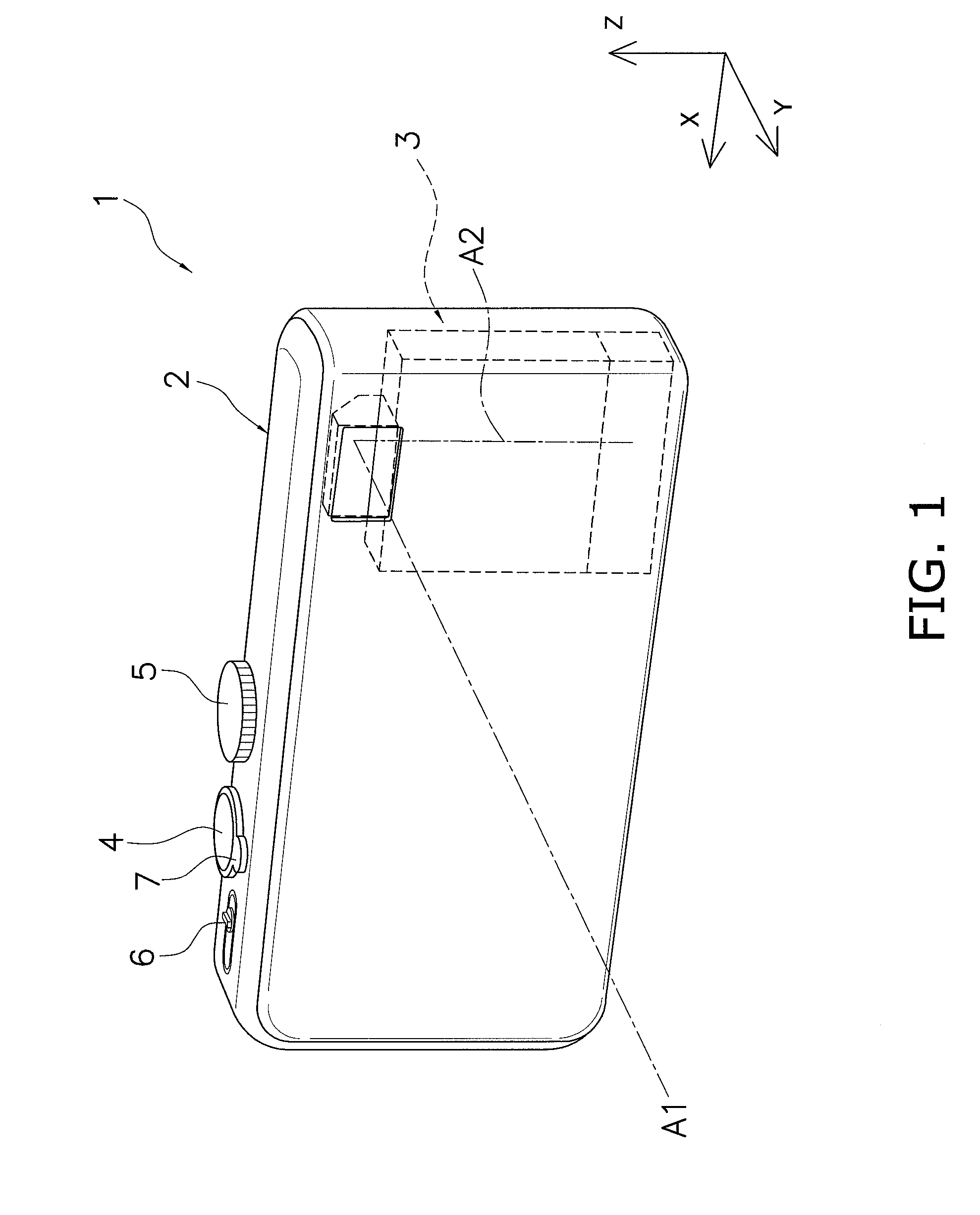
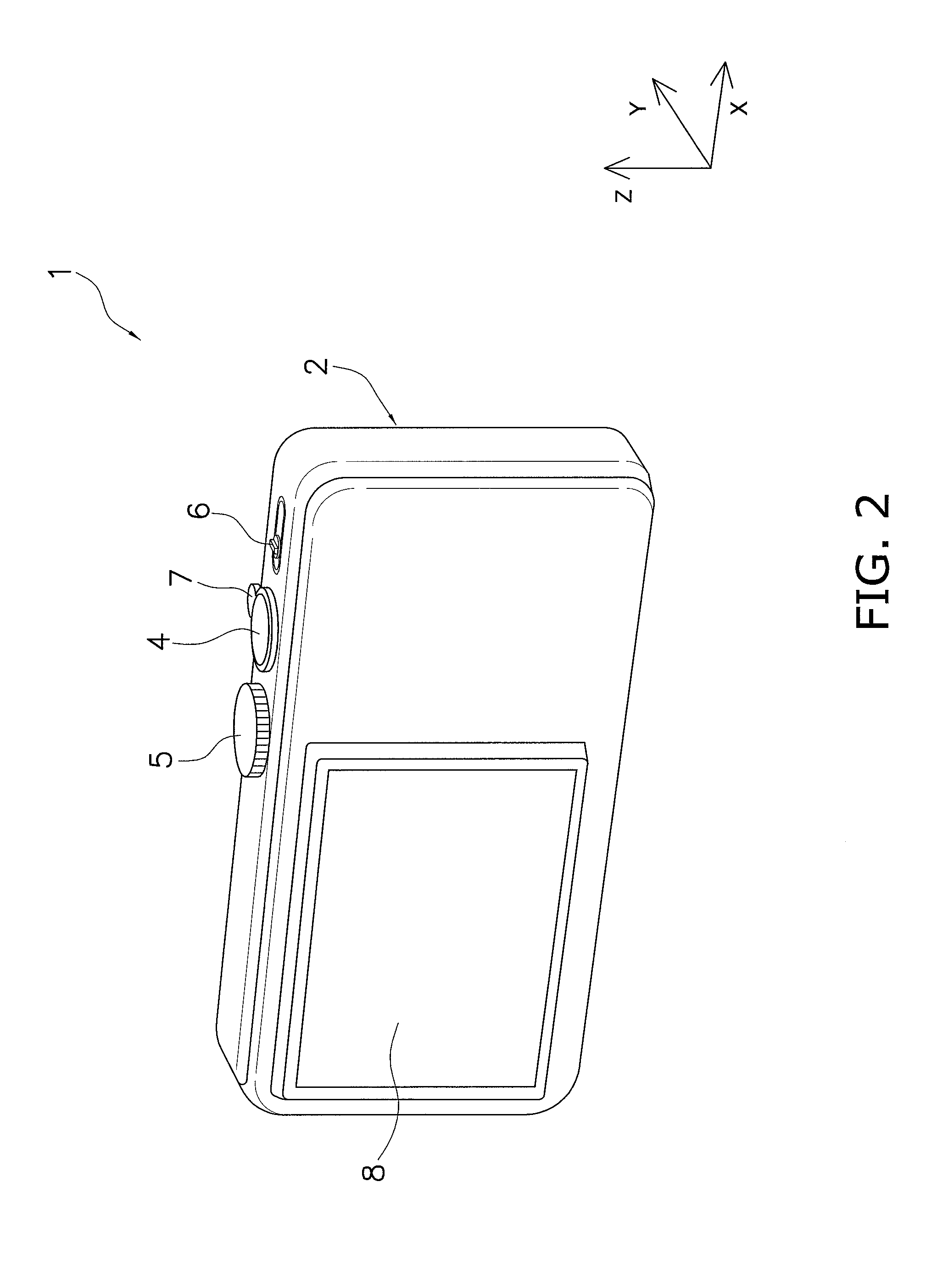
[0085]A digital camera 1 according to an embodiment of the present invention will now be described through reference to FIGS. 1 and 2. FIGS. 1 and 2 are simplified perspective views of the digital camera 1.

[0086]The digital camera 1 is a camera for capturing an image of a subject, and employs a bending optical system for boosting magnification and reducing the overall size.

[0087]In the following description, the six sides of the digital camera 1 are defined as follows.

[0088]The side facing the subject when an image is being captured by the digital camera 1 is called the front face of a camera main body 2, and the face on the opposite side is called the rear face. When an image is captured such that the top and bottom in the vertical direction of the subject match up with the top and bottom in the short-side direction of the rectangular image being captured by the digital camera 1 (the aspect ratio (the ratio of long to short sides) is generally 3:2, 4...


PUM


Abstract

A lens barrel is provided with which manufacturing costs can be reduced. The lens barrel (3) has a first lens group (G1), a second lens group (G2), a third lens group (G3), a first support frame (10) that supports the first lens group (G1), a second support frame (20) that supports the second lens group (G2), a third support frame (30) that supports the third lens group (G3), a first driving unit (50), a second driving unit (60), and a shutter unit (29) that is fixed to the second support frame (20). The first lens group (G1) has an overall negative refractive power, and includes a prism (PR). The second support frame (20) is driven along a second optical axis (A2) by the first driving unit (50). The third support frame (30) is driven along the second optical axis (A2) by the second driving unit (60).

Description

TECHNICAL FIELD[0001]The present invention relates to a lens barrel having a bending optical system.BACKGROUND ART[0002]Digital cameras that make use of imaging elements have become very popular in recent years. With digital camera, there has been a need not only for a greater number of pixels in the imaging elements, but also for higher performance of the lens barrel, which forms an optical image on the imaging elements. More specifically, there is a need for a lens barrel equipped with a higher-power zoom lens system.[0003]Meanwhile, in the field of digital camera, the main body needs to be made smaller in order to make the product more portable. There is therefore a need for a more compact imaging device equipped with a lens barrel and an imaging element, which should contribute greatly to the goal of obtaining a smaller main body. To reduce the size of an imaging device, a so-called bending optical system has been proposed in which the optical path is bent along the zoom lens sy...

Claims


Application Information

Patent Timeline
IPC IPC(8): G02B7/04
CPCG02B7/102G03B9/06G02B15/177G02B15/1445
Inventor ITO, DAISUKE
Owner PANASONIC CORP
Why Eureka
Try Eureka