Fluid dynamic bearing system

a dynamic bearing and fluid-filled technology, applied in sliding contact bearings, instruments, record information storage, etc., can solve the problems of not being able to detect the level of the fluid column within the sealing gap, not enough bearing fluid is filled into some bearings and too much is filled into others, and the cover cap prevents any optical inspection of the filling level of the bearing fluid. , to achieve the effect of convenient filling

Active Publication Date: 2010-11-04
MINEBEAMITSUMI INC
View PDF15 Cites 9 Cited by
  • Summary
  • Abstract
  • Description
  • Claims
  • Application Information

AI Technical Summary

Benefits of technology

[0003]The object of the invention is to provide a fluid dynamic bearing having the type of construction as descr...

Problems solved by technology

This filling method gives rise to the problem that after filling, the filling level, i.e. the level of the fluid column within the sealing gap, cannot be detected since the covering cap makes it impossible to see into the bearing gap.
However, since the bearings are subject to geometric dimensional deviation...

Method used


Image

  • Fluid dynamic bearing system
  • Fluid dynamic bearing system
  • Fluid dynamic bearing system

Examples


Embodiment Construction

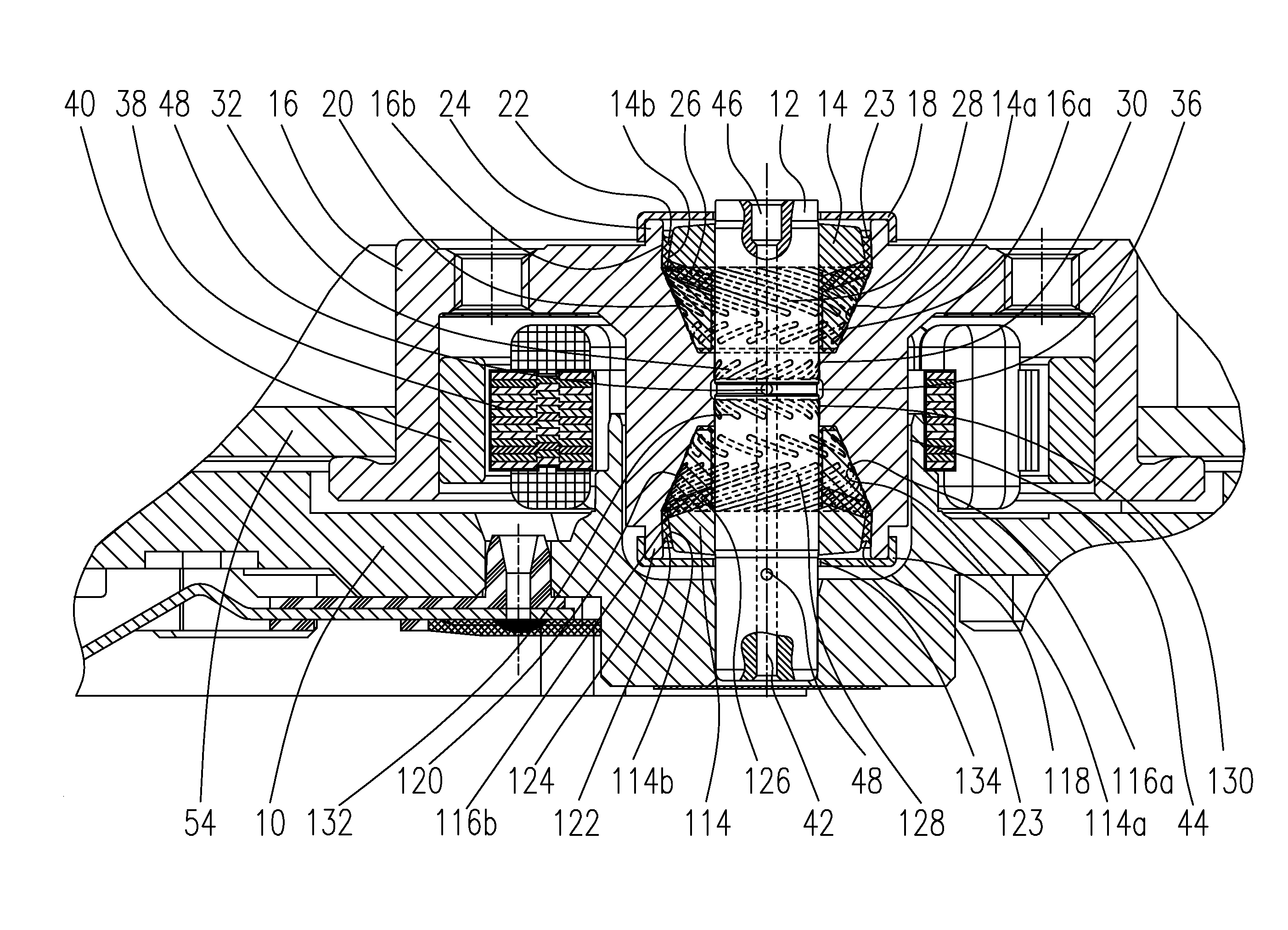
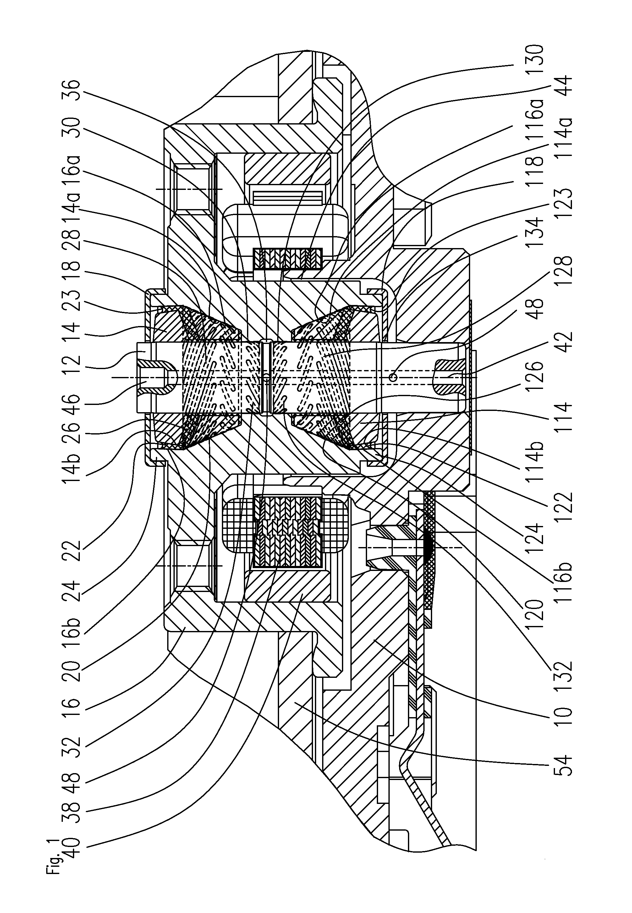
[0021]FIG. 1 shows a section through a spindle motor having a fluid dynamic bearing system according to the invention. The spindle motor comprises a baseplate 10 having a bore in which a shaft 12 is fixedly accommodated. The bearing system takes the form of a conical bearing system having two bearing components working in opposition to each other and having conical bearing surfaces. Two bearing cones 14, 114 are disposed on the shaft 12 at an axial distance from one another. The upper free end of the shaft 12 may be connected to a stationary component (not illustrated), which could, for example, be a housing component.

[0022]Each bearing cone 14, 114 has an annular bearing surface 14a, 114a set at an inclination to the rotational axis 42. A further bearing component taking the form of a rotor component 16 is disposed rotatable about the rotational axis 42 with respect to the bearing cones 14, 114. The rotor component 16 also has annular bearing surfaces 16a, 116a set at an inclinatio...


PUM


Abstract

The invention relates to a fluid dynamic bearing system having a first conical bearing and a second conical bearing working in opposition to the first conical bearing, wherein the two conical bearings are disposed along a stationary shaft, wherein the first and the second conical bearing each comprises a bearing cone disposed on the shaft having bearing surfaces as well as a conical counter bearing disposed in a rotor component that are separated from one another by a bearing gap filled with a bearing fluid, wherein the bearing gap has a first open end that is sealed by a first sealing gap partially filled with bearing fluid, wherein the bearing fluid in the sealing gap forms a fluid meniscus. According to the invention, the sealing gap is bounded by sealing surfaces of the bearing cone and associated sealing surfaces of the rotor component, wherein the smallest radius R1 of the sealing surfaces of the rotor component is larger than the largest outer radius R2 of the bearing cone and larger than the greatest possible distance R3 of the fluid meniscus from the rotational axis.

Description

BACKGROUND OF THE INVENTION[0001]The invention relates to a fluid dynamic bearing system, particularly a fluid dynamic bearing system having conical bearings that may be used in particular for the rotatable support of a spindle motor. Spindle motors having these kinds of fluid dynamic bearings are used, for example, for driving hard disk drives or fans.PRIOR ART [0002]US 2004 / 0005101 A1 discloses a fluid dynamic bearing system having two conical bearings working in opposition to each other. Each conical bearing has a bearing cone disposed on a stationary shaft that interacts with a counter bearing that is disposed in a rotor component. The bearing surfaces of each conical bearing are separated from one another by an individual bearing gap filled with a bearing fluid. The bearing gaps of the two conical bearings each have two open ends, each open end being sealed by a tapered sealing gap partially filled with bearing fluid. The inner sealing gaps facing the other conical bearing are ...

Claims


Application Information

Patent Timeline
IPC IPC(8): F16C32/06G11B17/02H02K7/08
CPCF16C17/105F16C33/103F16C33/107F16C2370/12F16C2326/02G11B19/2036F16C33/745
Inventor EFINGER, WOLFGANGBOSNJAK, MATTHIAS
Owner MINEBEAMITSUMI INC
Why Eureka
Try Eureka