Pulse-level interleaving for UWB systems

a pulse-level interleaving and pulse-level technology, applied in the direction of transmission, electrical equipment, etc., can solve the problems of receivers not being able to determine the proper word, limited range at which uwb pulse signals can typically be detected, and burst transmission or reception errors

Inactive Publication Date: 2010-11-04
L 3 COMM INTEGRATED SYST
View PDF4 Cites 19 Cited by
  • Summary
  • Abstract
  • Description
  • Claims
  • Application Information

AI Technical Summary

Benefits of technology

[0022]FIGS. 9A-9E are more detailed signal diagrams for pulse-level interleaving...

Problems solved by technology

One problem that faces UWB applications, such as geographic asset location applications, is the limited range at which UWB pulse signals can typically be detected.
Another problem is the need to distinguish at a receiver multiple UWB transmission sources, for example, where multiple assets are being tracked at the same time.
Other problems als...

Method used


Image

  • Pulse-level interleaving for UWB systems
  • Pulse-level interleaving for UWB systems
  • Pulse-level interleaving for UWB systems

Examples


embodiment 100

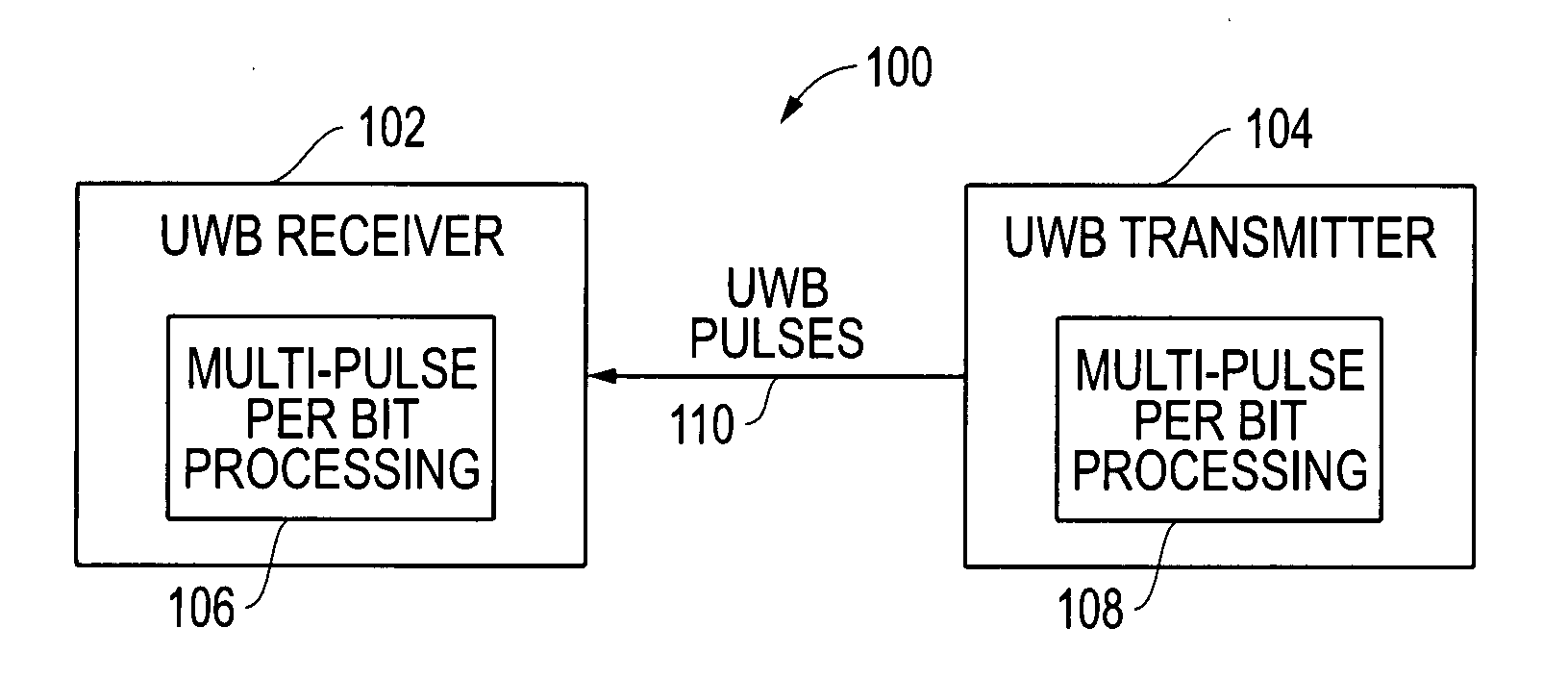
[0024]FIG. 1 is a block diagram for an embodiment 100 including a UWB transmitter 102 and UWB receiver 104 that utilize multi-pulse-per-bit processing and communications. As depicted, the UWB transmitter 104 includes multi-pulse-per-bit processing block 108, which operates to produce multiple UWB pulses for each data bit to be sent out by the UWB transmitter 104 as described in more detail below. The UWB transmitter transmits UWB pulses 110 that are then received by the UWB receiver 102. The UWB receiver 102 in turn includes a multi-pulse-per-bit processing block 106 that aggregates the energy associated with the multiple pulses in each bit frame, as described in more detail below, prior to detection of a received pulse. It is noted that the data bits can be part of a data packet, and data packets can be a any desired number of bits in size (e.g., 256 bit packets). It is further noted that transmitted pulses can be sent periodically within repeating time windows. For example, pulses...

embodiment 200

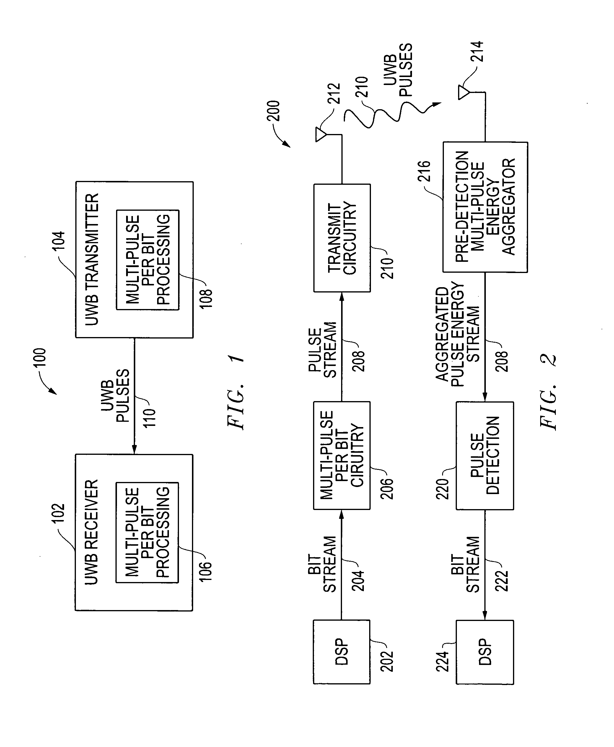
[0025]FIG. 2 is a block diagram for an embodiment 200 including a transmit path and a receive path that utilize multi-pulse-per-bit UWB pulse transmissions. Looking first to the transmit path, a digital signal processor (DSP) 202 produces a bit stream 204 that represents data desired to be output by the transmitter. The bit stream 204 is sent to multi-pulse-per-bit circuitry 206, which in turn produces a pulse stream 204 that includes multiple pulses for each data bit within the bit stream 204. Any desired number of multiple pulses can be utilized, for example, twenty (20) pulses per bit can be utilized. The pulse stream 208 is then sent to transmit circuitry 210, which produces the UWB pulses 110 that are transmitted from the transmit antenna 212 and received by the receive antenna 214.

[0026]Looking now at the receive path, the UWB pulses received at receive antenna 214 are sent to a pre-detection multi-pulse energy aggregator 216. This energy aggregator 216 operates to aggregate t...

embodiment 700

[0039]FIG. 7 is a data processing diagram 700 for pulse-level interleaving across multiple bit frames after multi-pulse-per-bit processing as described herein. As depicted, 4-bits of data 702 are desired to be transmitted. In the example depicted, these bits are “1001.” As described above, these bits are provided to multi-pulse-per-bit circuitry that generates multiple pulses for each data bit to be transmitted. In the embodiment 700, the number of pulses used per bit is twenty (20) and on-off keying (OOK) is utilized so that a logic “1” is represented by a pulse and a logic “0” is represented by the absence of a pulse. As depicted, the first bit “1” within the 4-bit data 702 is represented by 20 pulses within bit frame 704 from pulse window 0 to 20. The second bit “0” within the 4-bit data 702 is represented by 20 non-pulses within bit frame 706 from pulse window 21 to 40. The third bit “0” within the 4-bit data 702 is also represented by 20 non-pulses within bit frame 708 from pul...


PUM


Abstract

Systems and methods are disclosed that provide pulse-level interleaving for multi-pulse-per-bit ultra wideband (UWB) transmit and receive processing techniques to provide significantly improved multi-access for UWB systems and, more particularly, for long range UWB systems. A bit stream is processed such that each bit in a bit stream is represented by a plurality of bits in a bit frame and then transmitted using a plurality of UWB pulses for each bit frame. Where on-off-keying (OOK) modulation is used, each logic “1” is sent out as a plurality of pulses, and each logic “0” is sent out as a plurality of non-pulses. Pulse-level interleaving (PLI) of the pulses across multiple bit frames prior to transmission is provided to allow for improved multi-access (MA) by a plurality of UWB transmitters operating at the same time. Rather than attempt to detect each pulse as it arrives at the receiver, the receiver instead first de-interleaves the pulses and then aggregates the energy from the multiple pulses within each bit frame. The aggregated pulse energy is then processed by a pulse detector to detect a pulse. Where OOK modulation is used, this pulse detection detects the existence of a pulse or the lack of a pulse within the bit frame.

Description

RELATED APPLICATIONS[0001]This application is related in subject matter to the following concurrently filed applications: U.S. patent application Ser. No. ______, entitled “SYSTEMS AND METHODS FOR RFID TAG OPERATION” by Scott M. Burkart et al.; U.S. patent application Ser. No. ______, entitled “DATA SEPARATION IN HIGH DENSITY ENVIRONMENTS” by Jonathan E. Brown et al.; and U.S. patent application Ser. No. ______, entitled “SYSTEMS AND METHODS FOR GENERATING PULSED OUTPUT SIGNALS USING A GATED RF OSCILLATOR CIRCUIT” by Ross A. McClain et al.; each of which is each hereby incorporated by reference in its entirety.TECHNICAL FIELD OF THE INVENTION[0002]This invention relates to receiver and transmitter architectures for efficient wireless communications and, more particularly, to impulse radio receiver and transmitter architectures using ultra-wideband (UWB) pulses to transmit and receive information.BACKGROUND[0003]A wide variety of signals and related protocols exist for the use of rad...

Claims


Application Information

Patent Timeline
IPC IPC(8): H04B1/69
CPCH04B1/7163H04B1/71637H04B1/71635
Inventor WESTCOTT, BRYAN L.FUDGE, GERALD L.CHIVERS, MARK A.RAVINDRAN, SUJITMCCLAIN, JR., ROSS A.BURKART, SCOTT
Owner L 3 COMM INTEGRATED SYST
Why Eureka
Try Eureka