Method of monitoring a gas turbine engine

a gas turbine engine and monitoring method technology, applied in the direction of instruments, testing/monitoring control systems, process and machine control, etc., can solve the problems of inability to obtain direct measurement of engine thrust, limited or diminished usefulness of monitoring, etc., to improve engine operation efficiency

Active Publication Date: 2010-11-04
ROLLS ROYCE PLC
View PDF5 Cites 26 Cited by
  • Summary
  • Abstract
  • Description
  • Claims
  • Application Information

AI Technical Summary

Benefits of technology

[0017]Thereby determining engine deterioration and subs

Problems solved by technology

Unfortunately, with regard to gas turbine engines in service, that is to say with regard to an aircraft application on-wing, it is not possible to obtain a direct measurement of engine thrust.
Although monitoring of fuel flow at en

Method used


Image

  • Method of monitoring a gas turbine engine
  • Method of monitoring a gas turbine engine
  • Method of monitoring a gas turbine engine

Examples


Embodiment Construction

[0027]The description of an embodiment of aspects of the present invention is with regard to fuel flow changes but other indicators as engine performance parameters could be used.

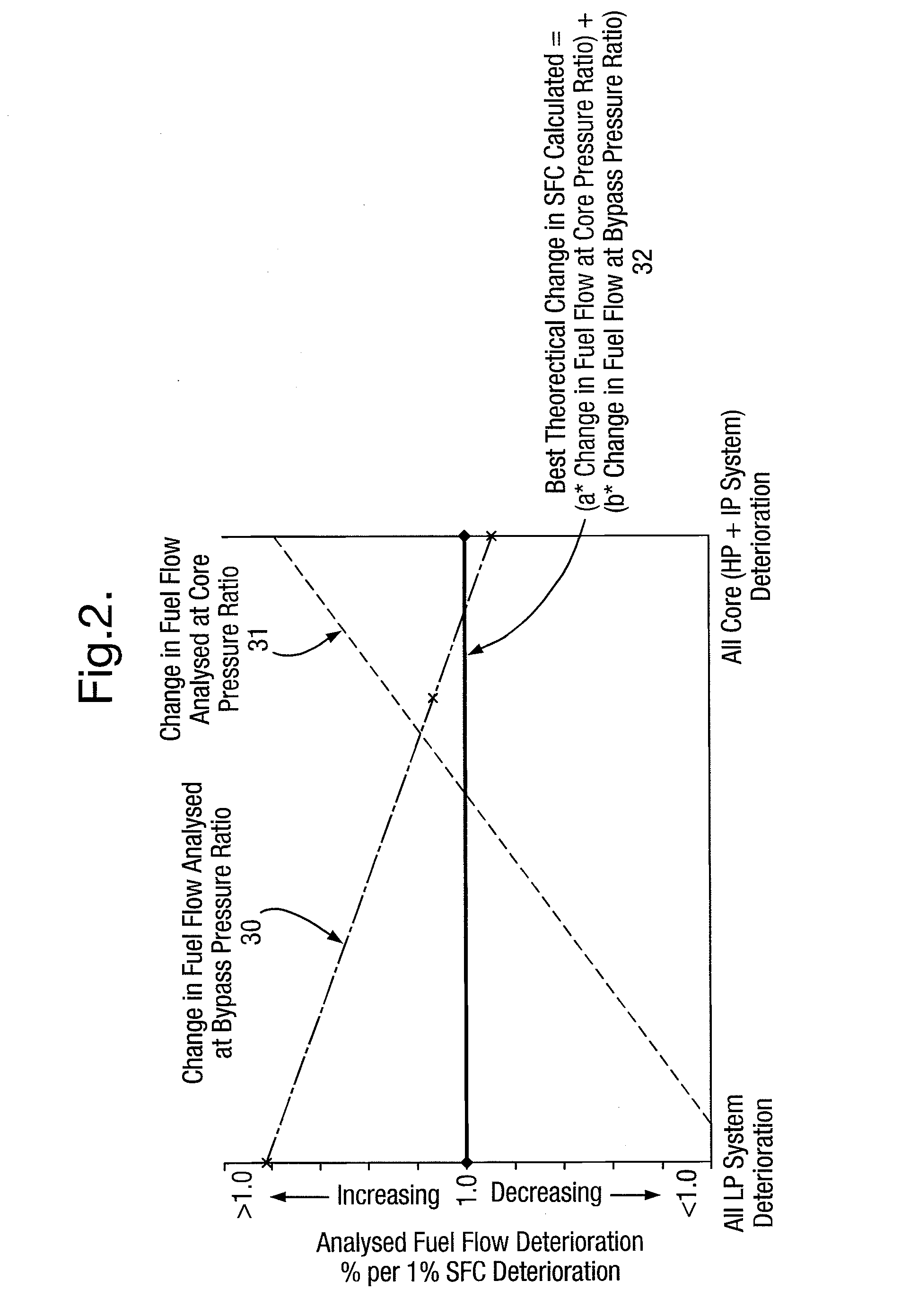
[0028]In accordance with aspects of the present invention, an improved approach to monitoring specific fuel consumption is provided based upon measurement of the engine fuel burn deterioration in use to provide an equivalency with regard to deterioration of engine specific fuel consumption. In such circumstances there is an improvement with respect to accuracy with regard to determining specific fuel consumption as an indicator or parameter of engine performance. As indicated above, variations in specific fuel consumption may be as a result of deterioration of the engine itself rather than lack of efficiency with regard to the engine performance. By monitoring or projecting deterioration of an engine and therefore scaling more accurate indicators with regard to specific fuel consumption as a result of such ...


PUM


Abstract

Operation of gas turbine engines and in particular gas turbine engines utilised for aircraft, in an efficient manner is a desired objective. Thus engine efficiency is typically determined through use of an engine performance parameter. One such engine performance parameter is with regard to specific fuel consumption. However, such parameters may vary as a result of inherent deterioration with regard to the engine. By utilising a computational model to determine variations in the performance parameter such as the specific fuel consumption changes as a result of such inherent engine degradation can be accommodate. Thus, such degradation may not swamp actual changes in fuel consumption or the engine performance parameter which are indicative of changes of engine efficiency. Generally and initially, computational results are utilised in order to provide a value with regard to degradation changes in the performance parameter, but such changes may be augmented by practical test results in order to tune the off-set constants a, b for an individual engine.

Description

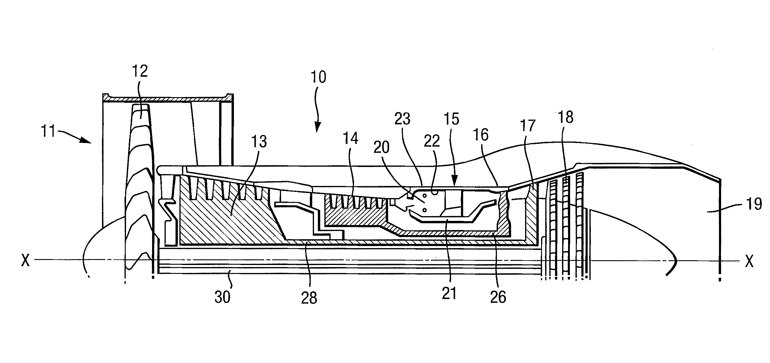
CROSS REFERENCE TO RELATED APPLICATION[0001]This application is entitled to the benefit of British Patent Application No. GB 0722398.5, filed on Nov. 15, 2007.FIELD OF THE INVENTION[0002]The present invention relates to methods of monitoring a gas turbine engine and more particularly with respect to monitoring engine performance parameters such as fuel consumption as an indicator of engine efficiency.BACKGROUND OF THE INVENTION[0003]Referring to FIG. 1, a gas turbine engine is generally indicated at 10 and comprises, in axial flow series, an air intake 11, a propulsive fan 12, an intermediate pressure compressor 13, a high pressure compressor 14, combustion equipment 15, a high pressure turbine 16, an intermediate pressure turbine 17, a low pressure turbine 18 and an exhaust nozzle 19.[0004]The gas turbine engine 10 works in a conventional manner so that air entering the intake 11 is accelerated by the fan 12 which produce two air flows: a first air flow into the intermediate pressu...

Claims


Application Information

Patent Timeline
IPC IPC(8): F02C9/00
CPCF02C9/28F05D2260/80G05B23/0243G05B17/02
Inventor PAGE, MICHAELWEBB, RICHARD LAWRENCEHOWARD, SCOTT FRAZER
Owner ROLLS ROYCE PLC
Why Eureka
Try Eureka