Architecture for a self-healing computer system

a computer system and self-healing technology, applied in the field of error detection in a computer system, can solve problems such as errors in digital logic associated with code blocks, and achieve the effect of preventing future processor errors

Active Publication Date: 2010-11-04
TOYOTA JIDOSHA KK
View PDF4 Cites 14 Cited by
  • Summary
  • Abstract
  • Description
  • Claims
  • Application Information

AI Technical Summary

Benefits of technology

[0011]The self-healing system is particularly advantageous because it provides a log including detailed information about digital logic errors that occur in the system. This information is accessible by engineers who provide real-time updates to the system using a network. For example, the log information is communicated from the system to an external system using a wireless network. In one embodiment, the external system is a component of the self-healing system. The se

Problems solved by technology

If the signatures do not match, then the digital

Method used


Image

  • Architecture for a self-healing computer system
  • Architecture for a self-healing computer system
  • Architecture for a self-healing computer system

Examples


first embodiment

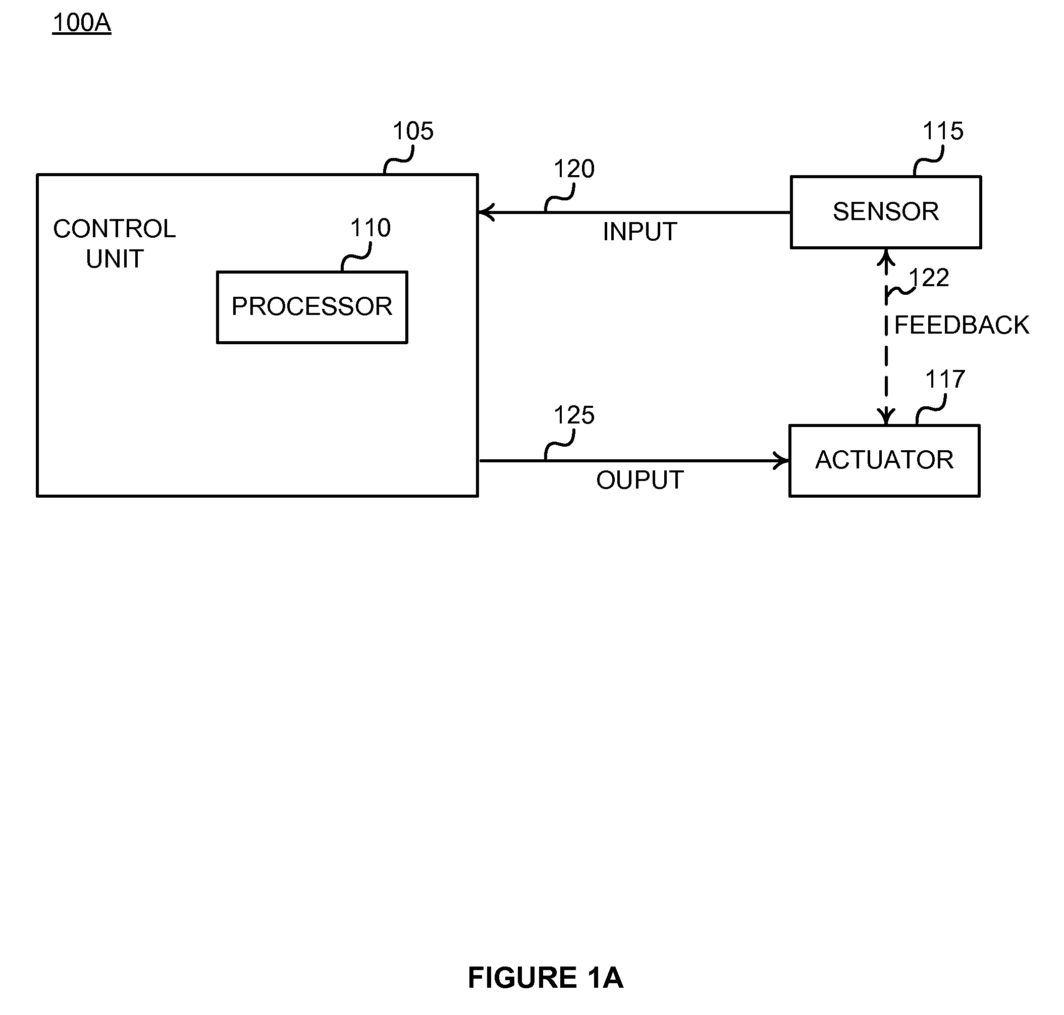
[0032]FIG. 1A shows a self-healing system 100A. This embodiment of the system 100 comprises a control unit 105 having a self-healing processor 110, a sensor 115, and an actuator 117. Signal line 120 couples the sensor 115 to the control unit 105 to send an input signal. Signal line 125 couples the control unit 105 to the actuator 117 to send an output signal. In some embodiments, a feedback signal is sent on signal line 122 between the sensor 115 and the actuator 117. While only one sensor 115, actuator 117, signal line 120, signal line 125 and signal line 122 are shown in FIG. 1 in order to simplify and clarify the description, those skilled in the art will recognize that any number of sensors 115 and / or actuators 117 may be coupled to control unit 105.

[0033]The control unit 105 is communicatively coupled to the sensor 115 via signal line 120. The control unit 105 is also communicatively coupled to the actuator 117 via signal line 125. The control unit 105 is an electronic device t...

second embodiment

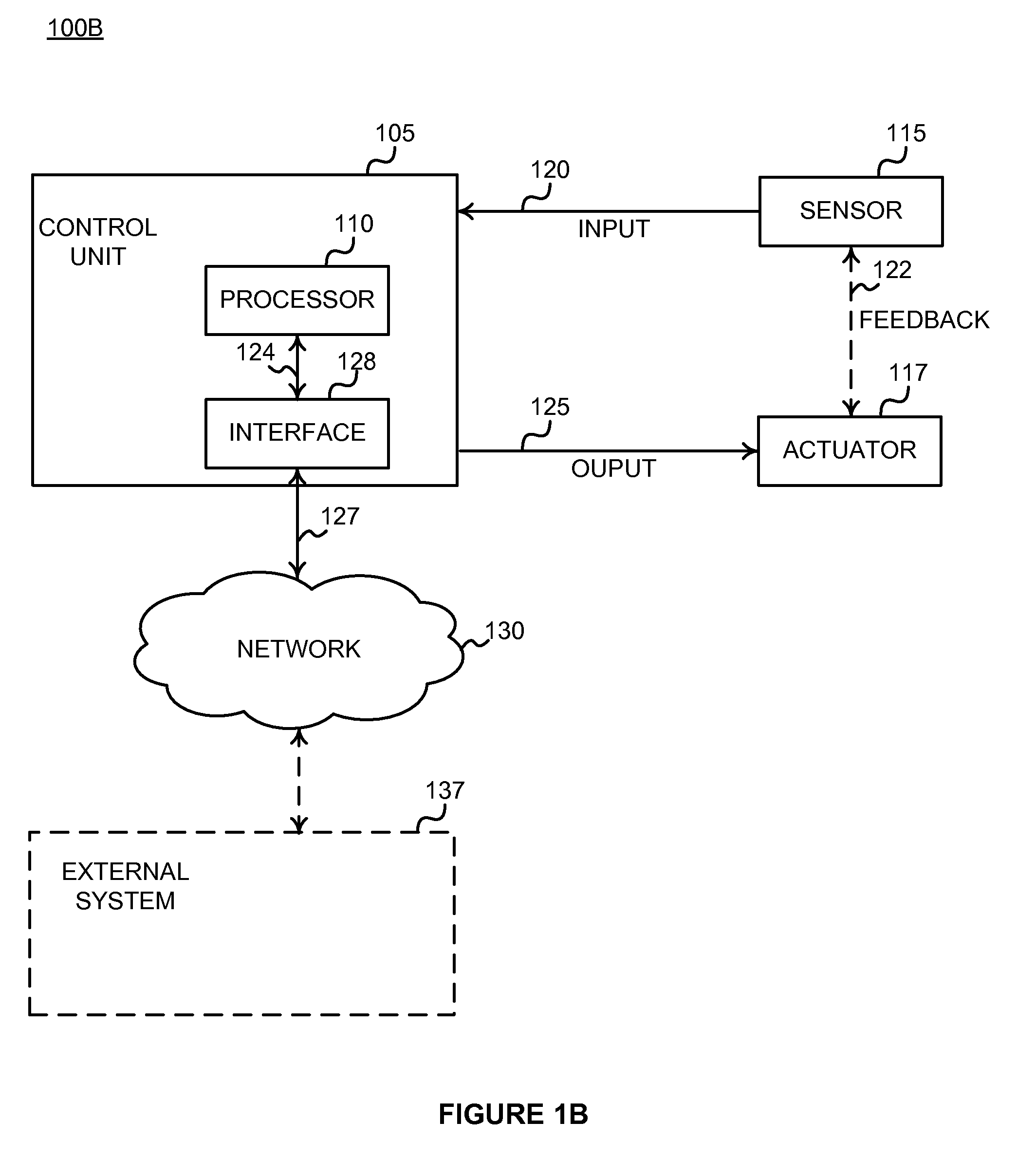
[0041]FIG. 1B shows the self-healing system 100. This embodiment of the self-healing system 100 comprises: the control unit 105; the self-healing processor 110; the sensor 115; the actuator 117; the signal line 120; the signal line 125; the signal line 122 (optional); an interface 128; a data signal 124; a communications coupling 127; a network 130; and an external system 137.

[0042]The interface 128 is adapted for communication with a network 130 via communications coupling 127. In one embodiment, the communications coupling 127 is a wireless communications link coupling the control unit 105 to the network 130. For example, the communications coupling 127 can be a wireless communication link coupling the interface 128 to the network 130. The network 130 enables communications among the entities connected to it. In one embodiment, the network 130 is the Internet and uses standard communications technologies and / or protocols. Thus, the network 130 can include links using technologies ...

third embodiment

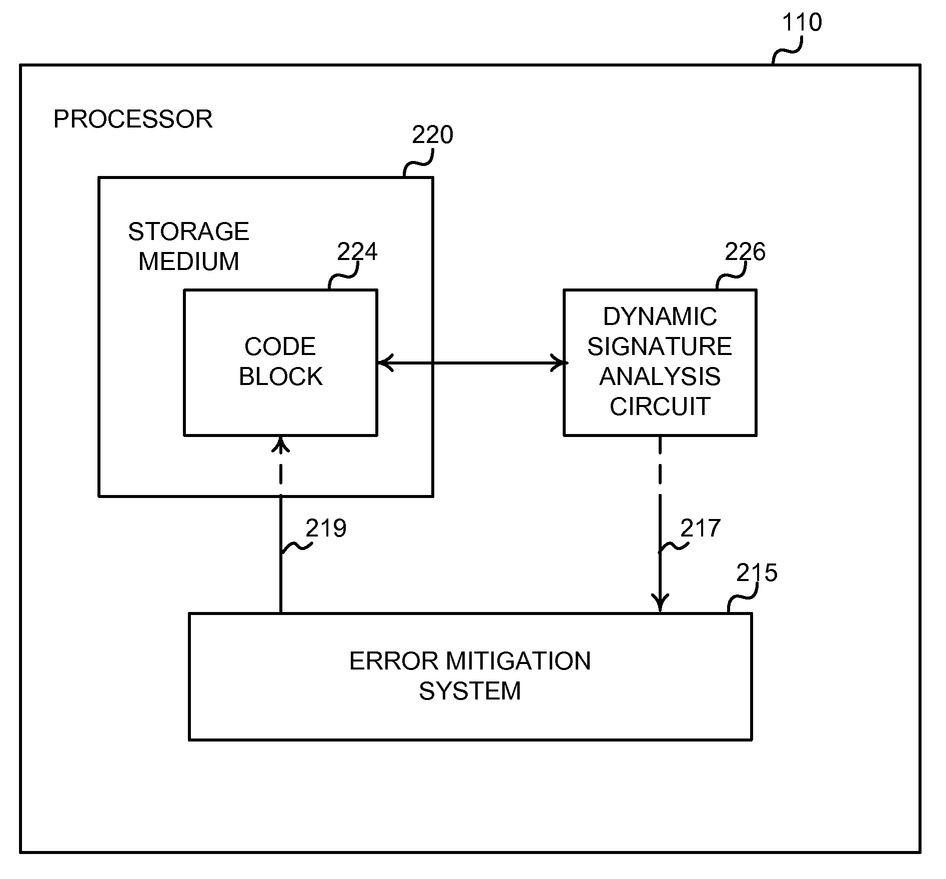
[0087]FIG. 4C shows the error mitigation system 215C. In this embodiment the error mitigation system 215C comprises: the static signature module 402; the monitor module 403; the comparison module 407; the retry module 409; the hardware controller 411; the lookup table 413; the set of alternative configurations 415; the strategy module 417; the persistent error module 421; the log module 437; and a set of emulation software 422B. Thus, in this embodiment, the persistent error mitigation assets 422A are a set of emulation software 422B.

[0088]Emulation software 422B is software that is configured to duplicate the functions of digital logic. In one embodiment, the persistent error module 421 communicates with the emulation software 422B. The persistent error module 421 then configures the emulation software 422B to duplicate the functionality described by the highest ranked alternative configuration 415 for the given retry attempt. The persistent error module 421 then executes the emula...


PUM


Abstract

The self-healing system comprises a self-healing processor and an error mitigation system. The self-healing processor includes a code block associated with the operation of a portion of digital logic. The self-healing processor also includes a dynamic signature analysis circuit. The processor executes the code block. The dynamic signature analysis circuit creates a dynamic signature representing the operation of the portion of digital logic associated with the code block. The error mitigation system receives the dynamic signature from the dynamic signature analysis circuit. The error mitigation system compares the dynamic signature to a static signature to determine if the signatures match. If the signatures do not match, then the digital logic associated with the code block has an error. The error mitigation system retries execution of the code block. The error mitigation system stores log information describing the above events.

Description

BACKGROUND OF THE INVENTION[0001]1. Field of the Invention[0002]The invention relates to error detection in a computer system, and more particularly, to an architecture for a computer system having self-healing functionality for detecting, mitigating and storing information about digital logic errors.[0003]2. Background of the Invention[0004]Modern automobiles frequently are designed to utilize numerous electronic control units (“ECUs”). Some automobiles include more than seventy ECUs. An ECU is a processor-based system that controls one or more of the electrical systems or subsystems in an automobile. For example, ECUs control fuel injection and ignition timing functions in the internal combustion engine of most automobiles. These functions are critical to automobile operation, and their failure could have potentially life-threatening repercussions for the human users of the automobile.[0005]A current trend is to design ECUs to use processors based on smaller geometry transistors. ...

Claims


Application Information

Patent Timeline
IPC IPC(8): G06F11/14G06F15/16
CPCG06F11/0739G06F11/0793G06F11/079
Inventor MELEN, ROGER D.MOUSSA, NADER W.HONDA, MAKOTOIKAI, HIDEOKATO, KOZO
Owner TOYOTA JIDOSHA KK
Why Eureka
Try Eureka