
Power Management Events Profiling

Active Publication Date: 2010-11-04
TEXAS INSTR INC
View PDF5 Cites 59 Cited by
  • Summary
  • Abstract
  • Description
  • Claims
  • Application Information

AI Technical Summary

Problems solved by technology

Yet increasing chip integration and rising focus on power management has created new challenges that were not considered when the standard was originally developed.

Method used


Image

  • Power Management Events Profiling
  • Power Management Events Profiling
  • Power Management Events Profiling

Examples


Embodiment Construction

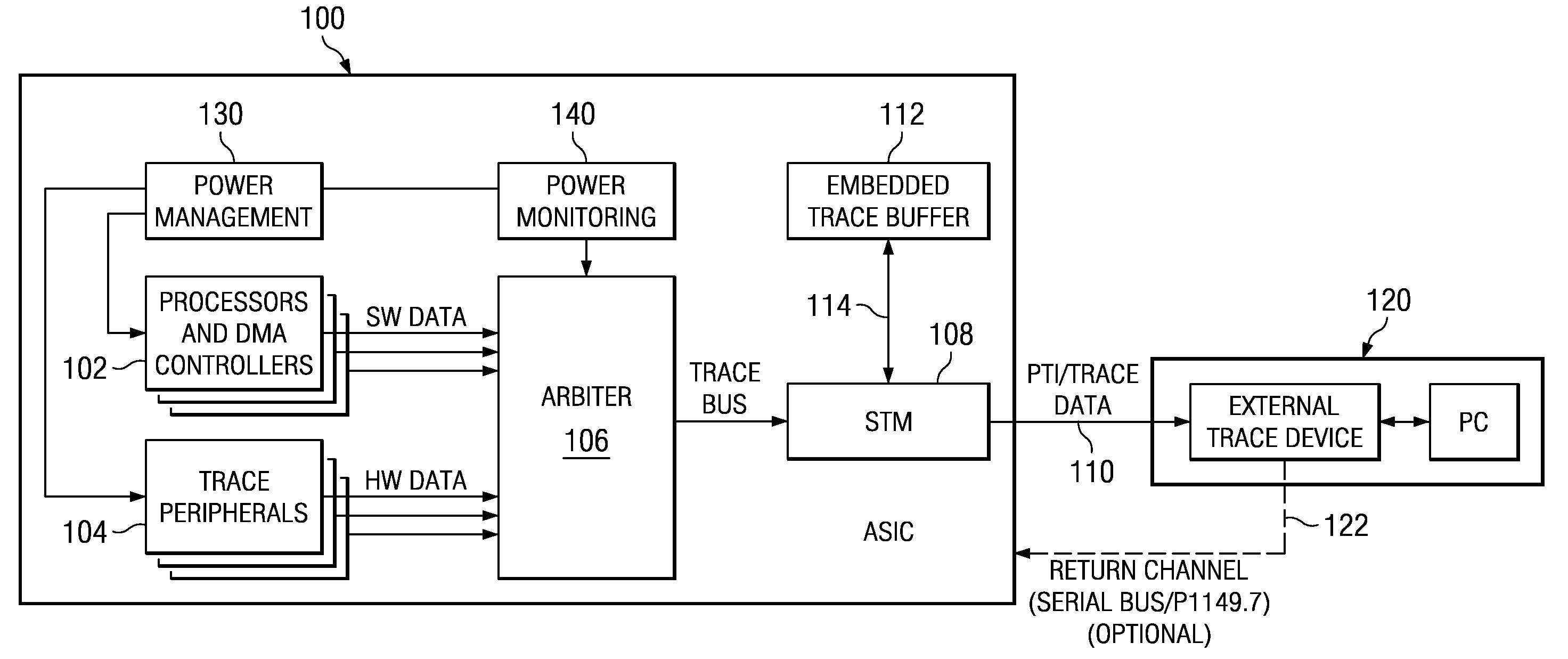
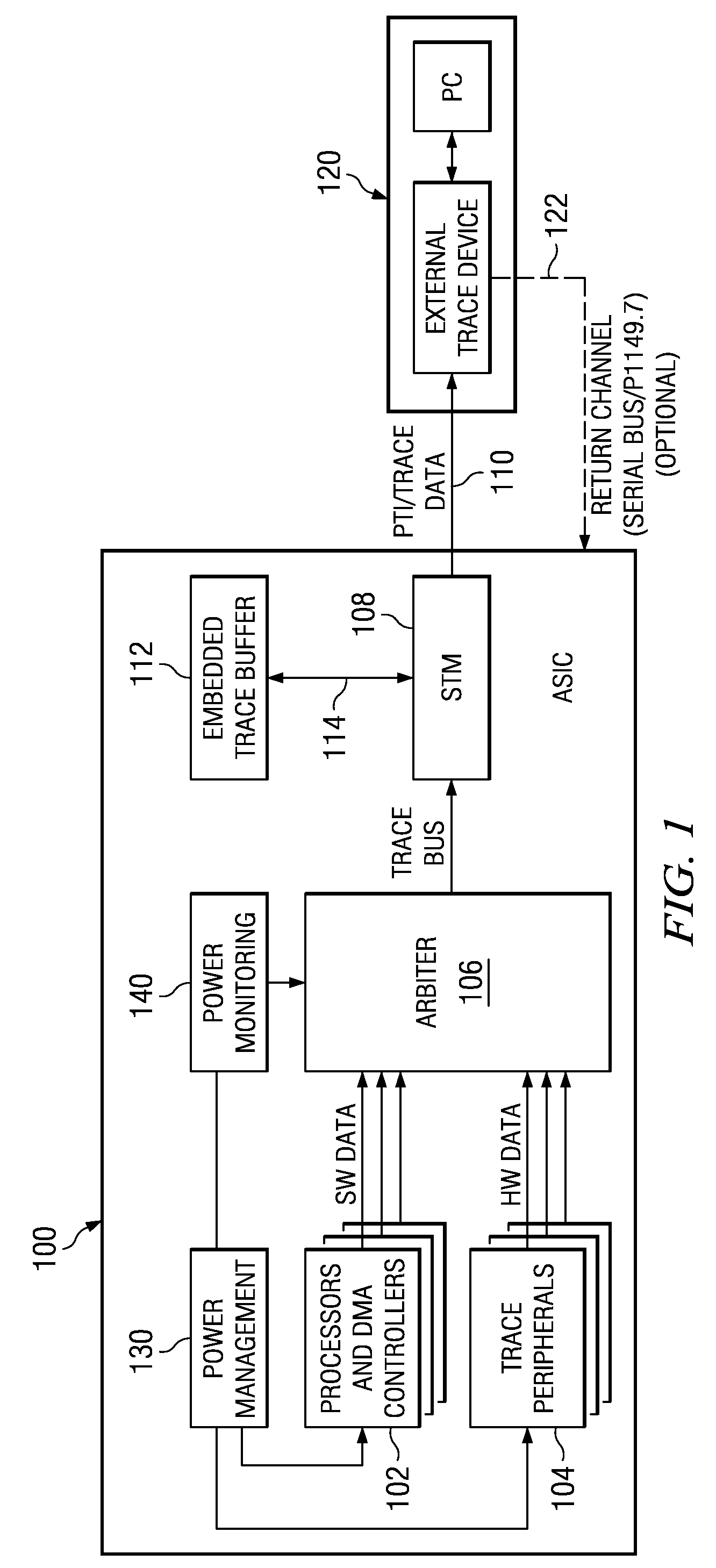
[0028]In order to test and debug a new application specific integrated circuit (ASIC) or a new or modified application program running on an ASIC, various events that occur during execution of an application or a test program are traced and made available to external test equipment for analysis. A time stamp is formed to associate with each trace event of a sequence of trace events. Embodiments of the present invention provide a scheme taking advantage of the system trace infrastructure to provide to the user visibility on the major power management (PM) events. The PM state changes are handled as generic events and encapsulated in system trace protocol (STP) messages and exported through the system trace module (STM) module. The nature of the power management events doesn't require accurate time stamping, therefore time stamp is handled at the STM or at the trace receiver level.

[0029]Embodiments of the present invention provide visibility into increasingly complex SOCs (system on a...


PUM


Abstract

In a method for monitoring power consumption by a system within an integrated circuit, one or more software programs are executed on the system on a chip (SOC). While the program executes, power control settings of a plurality of functional units within the SOC may be adjusted in response to executing the one or more software programs, whereby power consumption within the SOC varies over time. The power control settings may be changed in response to explicit directions from the executing software, or may occur autonomously in response to load monitoring control modules within the SOC. A sequence of power states is reported for the plurality of functional units within the SOC. Each of the sequence of power states may include clock frequencies from multiple clock domains, voltage levels for multiple voltage domains, initiator activity, target activity, memory module power enablement, or power enablement of each of the plurality of functional units.

Description

CLAIM OF PRIORITY[0001]This application for Patent claims priority to European Patent Application No. EP 09 290 316.0 (Attorney docket TI-67157PS) entitled “Power Management Events Profiling” filed 30 Apr. 2009, and is incorporated by reference herein.FIELD OF THE INVENTION[0002]This invention generally relates to application software development, software integration, and system optimization of complex integrated circuits and in particular to tracing hardware power events, including voltage and clock frequency adjustments.BACKGROUND OF THE INVENTION[0003]Testing and debugging of a new application specific integrated circuit (ASIC) or of a new or modified application program running on an ASIC requires insight into the internal workings of busses and program execution. The IEEE 1149.1 (JTAG) standard has proven to be a very robust solution to a variety of test and debug systems, enabling a rich ecosystem of compliant products to evolve across virtually the entire electronics industr...

Claims


Application Information

Patent Timeline
Patent Type & Authority Applications(United States)
IPC IPC(8): G06F11/34G06F1/32
CPCG06F11/3013G06F11/3055G06F11/3093G06F11/3409G06F11/3476Y02B60/165G06F11/3636G06F11/3648G06F2201/86G06F2201/88G06F11/348Y02D10/00
Inventor LAURENTI, GILBERTCARDINI, DARIO
Owner TEXAS INSTR INC
Features
  • Generate Ideas
  • Intellectual Property
  • Life Sciences
  • Materials
  • Tech Scout
  • Unparalleled Data Quality
  • Higher Quality Content
  • 60% Fewer Hallucinations
Learn More