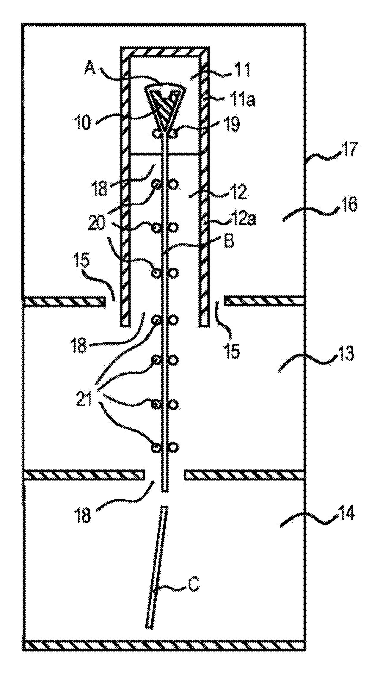
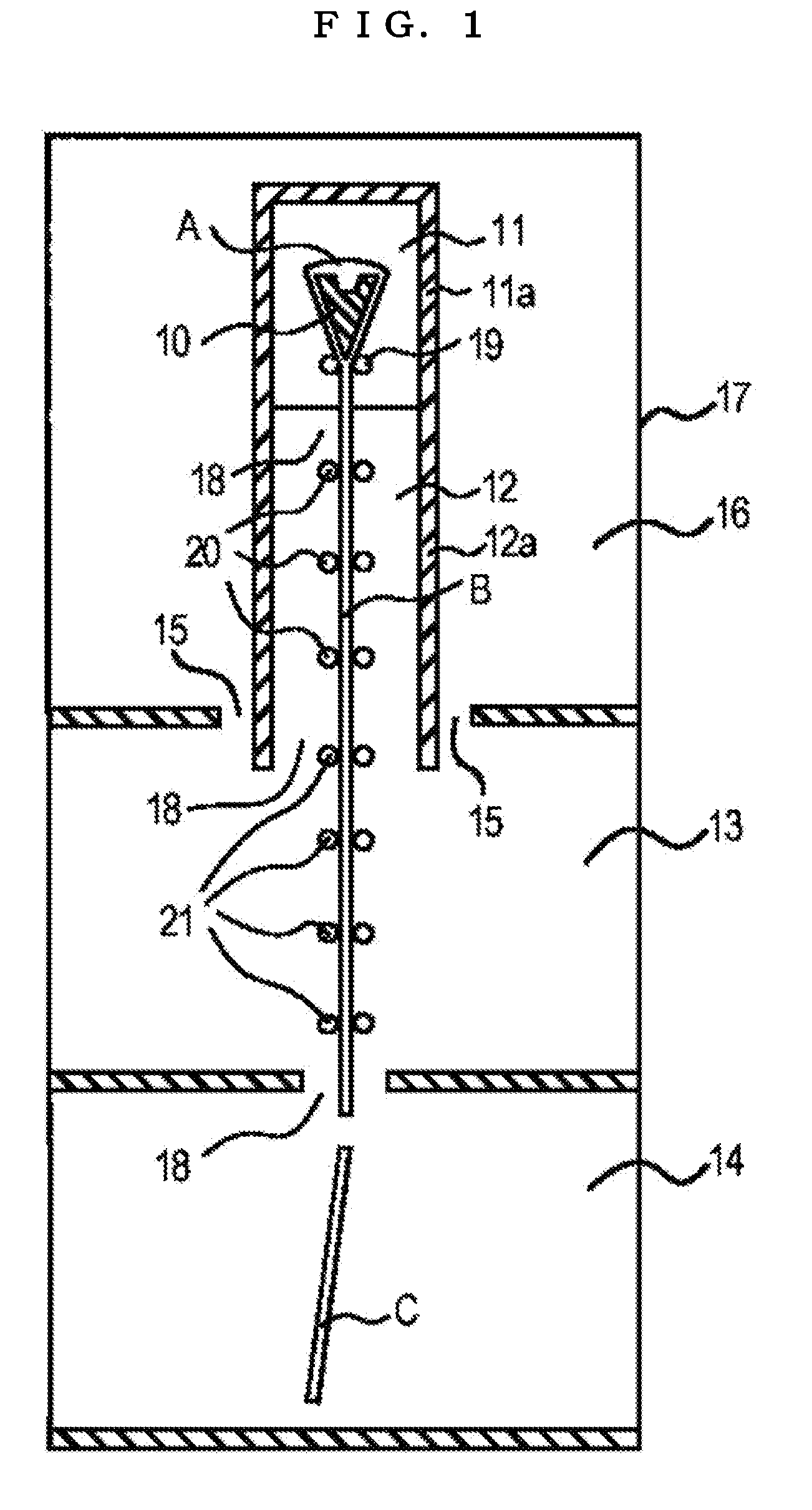
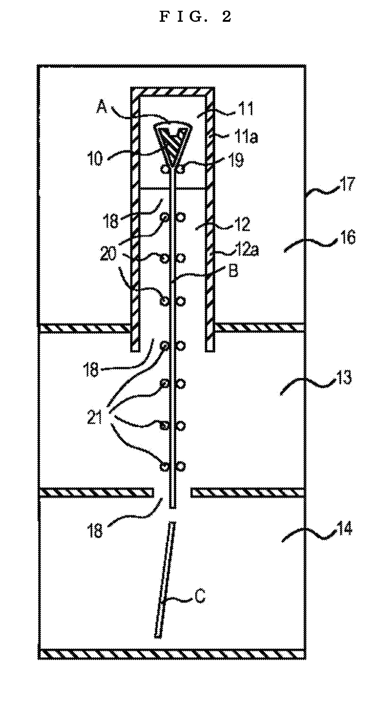
[0021]In the process for producing a glass sheet, which include a forming step of down-drawing a molten glass into a sheet-like glass ribbon, in which the molten glass is fed to a forming trough arranged in a forming furnace and the molten glass is caused to flow down from the forming trough through a conveyance passage extending vertically, an annealing step of removing an internal strain in the glass ribbon in an annealing furnace, a cooling step of cooling the glass ribbon to around
room temperature, and a
cutting step of cutting the glass ribbon in a given size, the invention according to claim 1 provides the cooling chamber with a gas exhausting passage to exhaust the air in the cooling chamber to the outside, to thereby allow the air in the cooling chamber to be exhausted while being dispersed into both of the conveyance passage of the glass ribbon and the gas exhausting passage, with the result that the
climb of low-temperature
airflow can be suppressed in the conveyance passage. As a result, the variation of the
atmospheric temperature in the annealing furnace can be suppressed to a minimum extent, leading to a sufficient reduction in the internal strain in a glass sheet even if the size of the glass sheet becomes large. The cooling chamber is preferably provided with the gas exhausting passage at its ceiling portion because the air-exhausting effect becomes larger.
[0022]The invention according to claim 2 allows the air in the cooling chamber to be exhausted to a chamber surrounding a forming furnace and / or an annealing furnace through the gas exhausting passage, to thereby elevate the pressure in the chamber surrounding a forming furnace and / or an annealing furnace. As a result, an effect of suppressing the
climb of the low-temperature
airflow in the conveyance passage of the glass ribbon becomes larger. That is, the low-temperature
airflow that has climbed from the cooling chamber into the annealing furnace is heated in the annealing furnace, and then part of the low-temperature airflow leaks into the outside
atmosphere through the gaps of furnace walls of the forming furnace and / or an annealing furnace. However, the elevation of the pressure in the chamber surrounding a forming furnace and / or an annealing furnace suppresses the leakage of the inside air of the forming furnace and / or annealing furnace. As a result, the effect of suppressing the
climb of the low-temperature airflow in the conveyance passage of the glass ribbon becomes larger.
[0023]By using the invention according to claim 3, the forming step is a step for forming a glass ribbon by an overflow down-draw method or a slot down-draw method and hence a thin plate glass can be efficiently formed. In order to obtain a plate glass particularly excellent in surface quality, it is desirable to employ the overflow down-draw method rather than the slot down-draw method. It should be noted that the slot down-draw method is a method involving supplying a molten glass to a forming trough having an aperture in a long-hole shape (slot shape), then pulling the molten glass out of the aperture of the forming trough to form a sheet-like glass ribbon, and vertically extending and forming the glass ribbon into a glass sheet.
[0024]Further, in the present invention, when the glass ribbon is
cut in a given size, the glass ribbon flowing down vertically may be
cut in the width direction of the glass ribbon (direction perpendicular to the flowing-down direction of the glass ribbon) from the cooling step, or the glass ribbon may be bent from the vertical direction to the horizontal direction and
cut in the width direction while being moved in the horizontal direction.
[0025]By using the invention according to claim 4, the glass sheet has a length of the short side of 2000 mm or more, and hence many glass sheets for a display panel can be cut out from one piece of the glass sheet (original sheet), enabling the improvement in the production efficiency. The larger the size of the glass sheet, the larger the internal strain of the glass sheet tends to be. One of the reasons for that is considered to be that when the size of the glass sheet becomes larger, the apparatus for producing a glass sheet has to be larger, resulting in the easiness for low-temperature air to flow in the conveyance passage of the glass ribbon, with the result that the variation of the
atmospheric temperature in the annealing furnace easily occurs. Thus, the present invention becomes useful when the invention is used for producing particularly large glass sheets, specifically, a glass sheet having a length of the short side of 2000 mm or more, preferably 2500 mm or more, or still more preferably 3000 mm or more.
[0026]By using the invention according to claim 5, the glass sheet has a maximum value of an internal strain of 1.0 MPa or less, and hence the image of a
liquid crystal display is prevented from becoming nonuniform due to
birefringence. By using the present invention, the variation of the
atmospheric temperature in the annealing furnace can be suppressed to a minimum extent, leading to the suppression of the internal strain in the glass sheet even if the size of the glass sheet becomes large. To be specific, it becomes possible to control the maximum value of the internal strain to 1.0 MPa or less, 0.8 MPa or less, or further 0.7 MPa or less.


