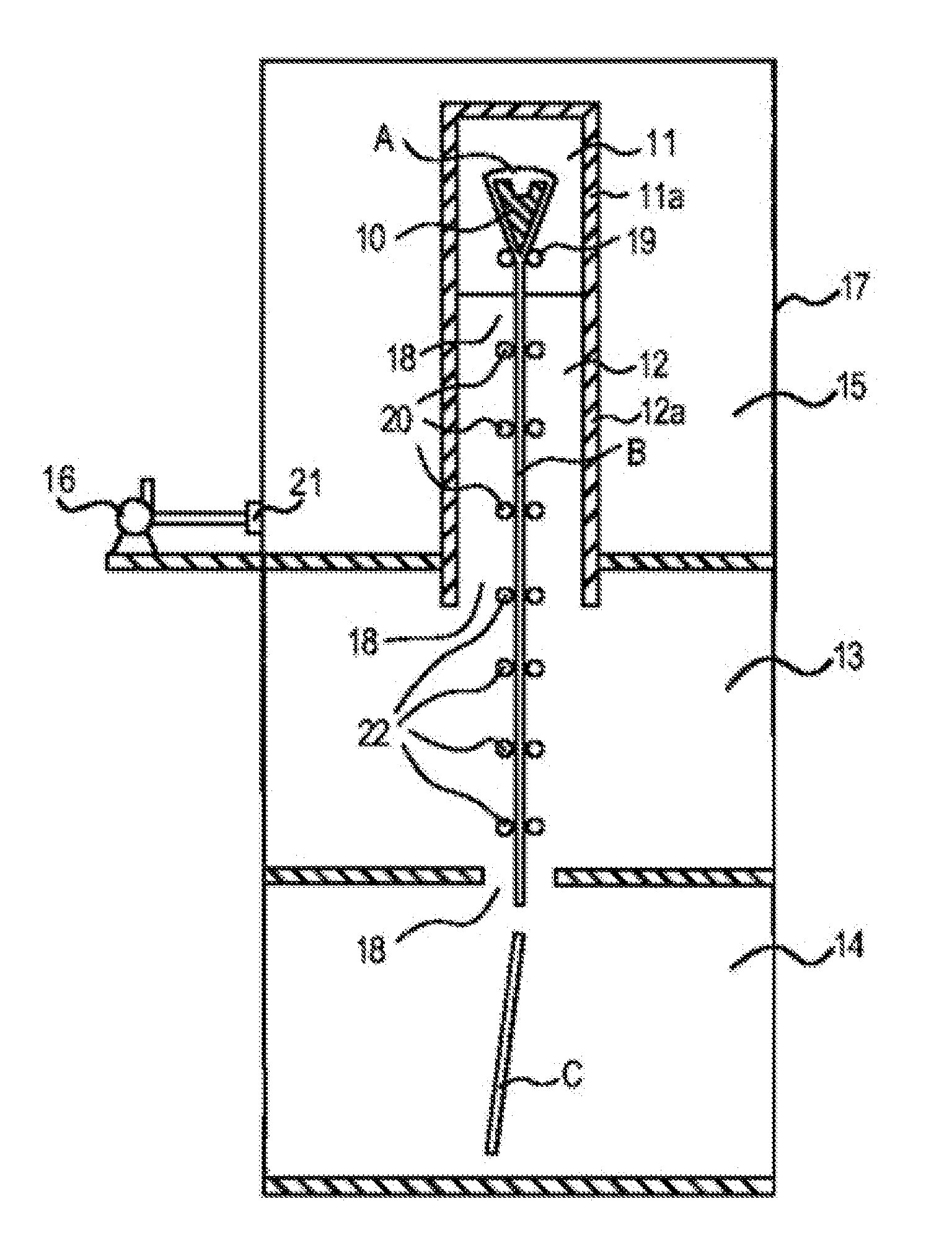
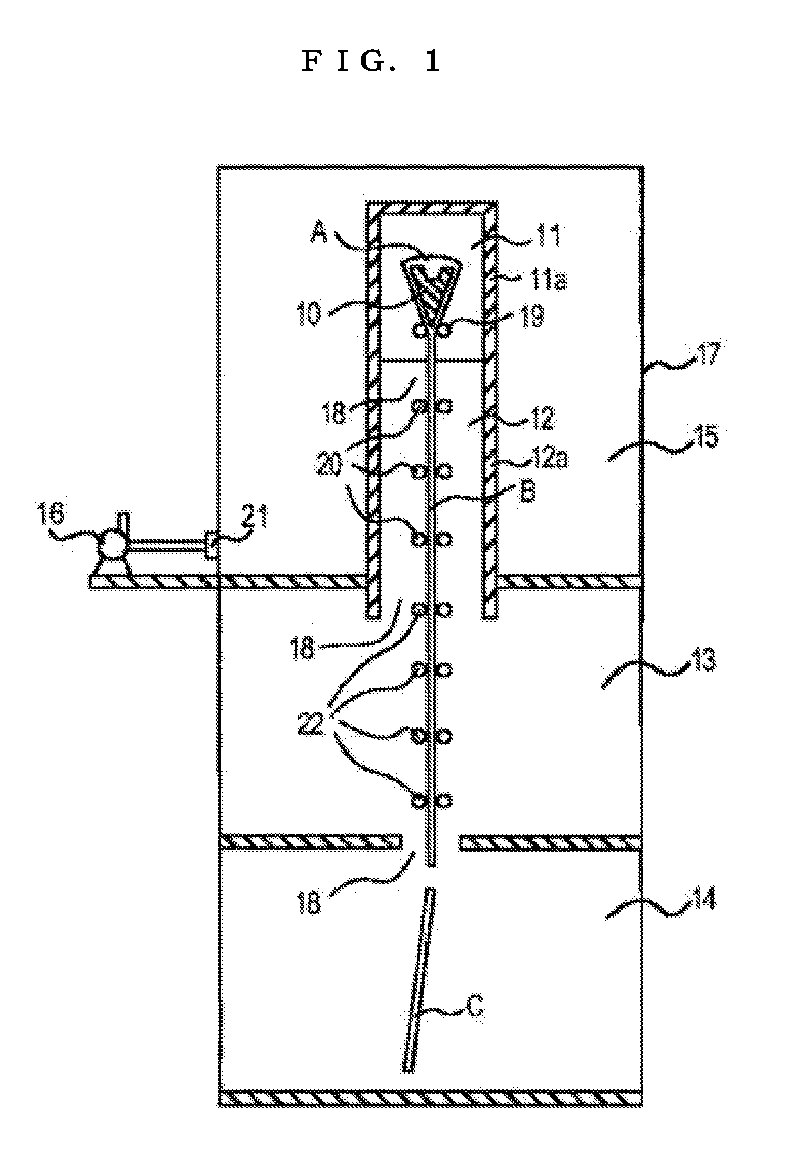
[0022]In the process for producing a glass sheet, which include a forming step of down-drawing a molten glass into a sheet-like glass ribbon, in which the molten glass is fed to a forming trough arranged in a forming furnace and the molten glass is caused to flow down from the forming trough through a conveyance passage extending vertically, an annealing step of removing an internal strain in the glass ribbon in an annealing furnace, a cooling step of cooling the glass ribbon to around
room temperature, and a
cutting step of cutting the glass ribbon in a given size, the invention according to claim 1 enables the elevation of the pressure in the outside
atmosphere of the forming furnace and / or the annealing furnace, providing a rare possibility for the inside air of the forming furnace and / or the annealing furnace to leak into the outside
atmosphere of the furnaces through the gaps of furnace walls, with the result that the
climb of low-temperature
airflow can be suppressed in the conveyance passage of the glass ribbon. As a result, the variation of the
atmospheric temperature in the annealing furnace can be suppressed to a minimum extent, leading to a sufficient reduction in the internal strain in a glass sheet even if the size of the glass sheet becomes large.
[0023]Here, the
phrase “elevation of the pressure in the outside atmosphere of a forming furnace and / or an annealing furnace” means elevating the pressure in the outside space (chamber) surrounding any one of the forming furnace and the annealing furnace or both furnaces by using a pressurizing unit. That is, the
phrase means that the pressure in the outside space is adjusted so that the outside space has a higher pressure than that provided when the pressurizing unit is not used. It is recommended that the pressure be suitably set to such an extent at which the amount of the leakage of the inside air in the forming furnace and the annealing furnace to the outside of the furnaces is reduced.
[0024]Further, the outside space surrounding any or both of the forming furnace and the annealing furnace may be constituted of one chamber or may be separated to two chambers. The outside space is required to keep its airtightness. When the outside space is separated to two chambers, for example, in the case where the forming furnace is surrounded by a forming chamber and the annealing furnace is surrounded by an annealing chamber, the pressure in the forming chamber and the pressure in the annealing chamber have to be adjusted independently.
[0025]In the process for producing a glass sheet which includes a forming step of down-drawing a molten glass into a sheet-like glass ribbon, in which the molten glass is fed to a forming arranged in a forming furnace and the molten glass is caused to flow down from the forming trough through a conveyance passage extending vertically, an annealing step of removing an internal strain in the glass ribbon in an annealing furnace, a cooling step of cooling the glass ribbon to around
room temperature, and a cutting step of cutting the glass ribbon in a given size, the invention according to claim 2 adjusts a pressure in an atmosphere in the forming furnace to be higher than that in an atmosphere in the cooling step, with the result that the
climb of low-temperature
airflow can be suppressed in the conveyance passage of the glass ribbon. As a result, the variation of the
atmospheric temperature in the annealing furnace can be suppressed to a minimum extent, leading to a sufficient reduction in the internal strain in a glass sheet even if the size of the glass sheet becomes large. As a unit of adjusting the pressure in the atmosphere in the forming furnace so as to be higher than that in the atmosphere in the cooling step in the downstream of the forming furnace, there can be used a method of elevating the pressure in the outside atmosphere in the forming furnace, a method of suppressing the leakage of air from the forming furnace to the outside atmosphere, a method of discharging the atmosphere in the cooling step to the outside, thereby reducing the amount of air climbing through the conveyance passage from the annealing furnace, or the like. Further, it is recommended that the difference in the pressure between the atmosphere in the forming furnace and the atmosphere in the cooling step be suitably selected depending on the scale of apparatuses and temperature conditions. For example, setting a difference of 0.001 atm or more (preferably 0.01 atm or more) provides a given effect.
[0026]The invention according to claim 3 allows the pressure in the outside atmosphere in the forming furnace and / or the annealing furnace to be elevated by introducing air from the outside, and hence the pressure in the outside atmosphere can be easily elevated by using a fan or the like. That is, a fan is installed outside the chamber surrounding the forming furnace and the annealing furnace, and air is introduced from outside the chamber with the fan, to thereby easily elevate the pressure in the outside atmosphere in the forming furnace and the annealing furnace.
[0027]By using the invention according to claim 4, the forming step is a step for forming a glass ribbon by an overflow down-draw method or a slot down-draw method and hence a thin plate glass can be efficiently formed. In order to obtain a plate glass particularly excellent in surface quality, it is desirable to employ the overflow down-draw method rather than the slot down-draw method. It should be noted that the slot down-draw method is a method involving supplying a molten glass to a forming trough having an aperture in a long-hole shape (slot shape), then pulling the molten glass out of the aperture of the forming trough to forma sheet-like glass ribbon, and vertically down-drawing the glass ribbon into a glass sheet.

