
Chemiluminescent impact activated projectile

a technology of chemiluminescent impact and projectile, which is applied in the direction of projectiles, ammunition projectiles, weapons, etc., can solve the problems of light production, reduce the likelihood of collateral damage or indirect injury, eliminate the use of pyrotechnics, and reduce the loss of the most intense portion of light production

Inactive Publication Date: 2010-11-11
CYALUME TECH
View PDF31 Cites 26 Cited by
  • Summary
  • Abstract
  • Description
  • Claims
  • Application Information

AI Technical Summary

Benefits of technology

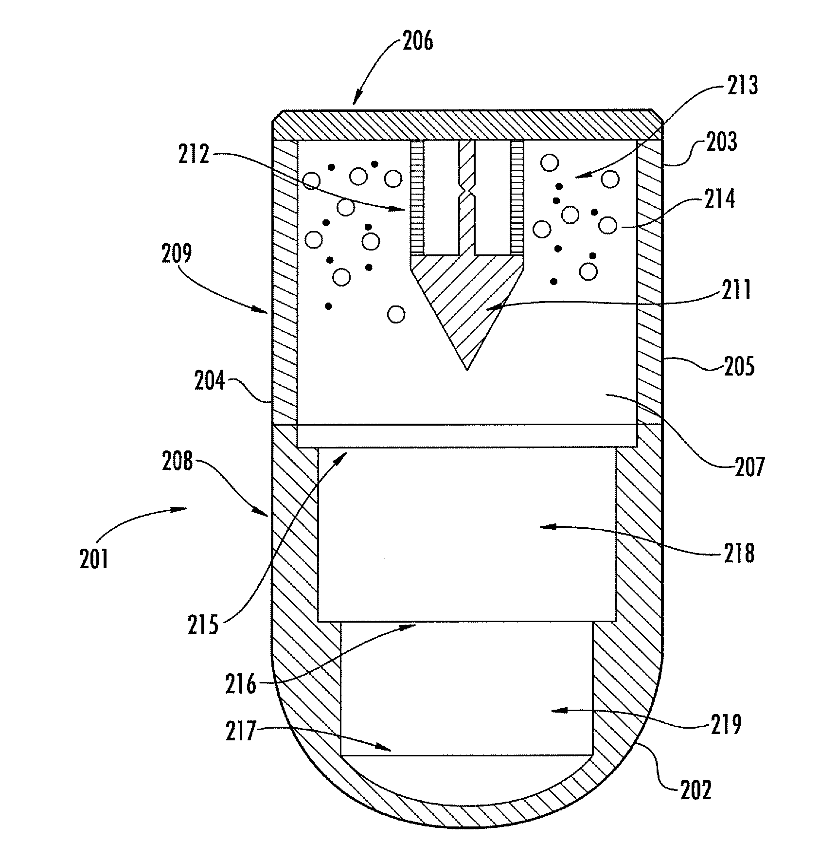
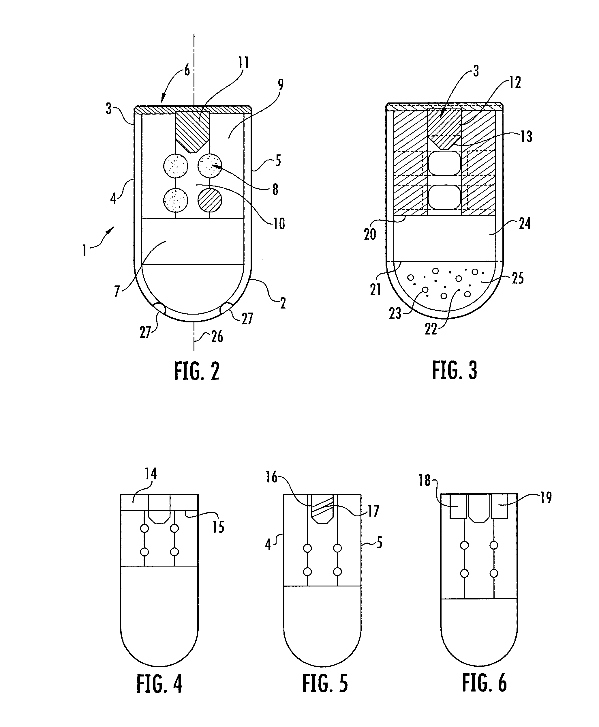
[0028]In a particular embodiment, the light emitting projectile for marking a target upon impact comprises a projectile body having a first end, a second end, a plurality of side walls, a base plate, and an interior portion therein. The inner portion includes chemiluminescent reactant components contained within a plurality of frangible containers which are exemplified as, albeit not limited to, a form of ampoules. At least one chemiluminescent reaction activator element is releasably attached to the base plate. Impact of the projectile with a target produces sufficient force to release the chemiluminescent reaction activator element within an inner channel. As the chemiluminescent reaction activator element moves within the inner channel, it contacts the ampoules. Contact of the ampoules results in releasing and intermixing of the chemiluminescent reactant components, resulting in the generation of light.
[0042]It is yet another objective of the instant invention to provide a chemiluminescent projectile which provides stealthy tactical and training applications.

Problems solved by technology

In either case, rupture of the containers causes intermixing and results in light production.

Method used


Image

  • Chemiluminescent impact activated projectile
  • Chemiluminescent impact activated projectile
  • Chemiluminescent impact activated projectile

Examples


Embodiment Construction

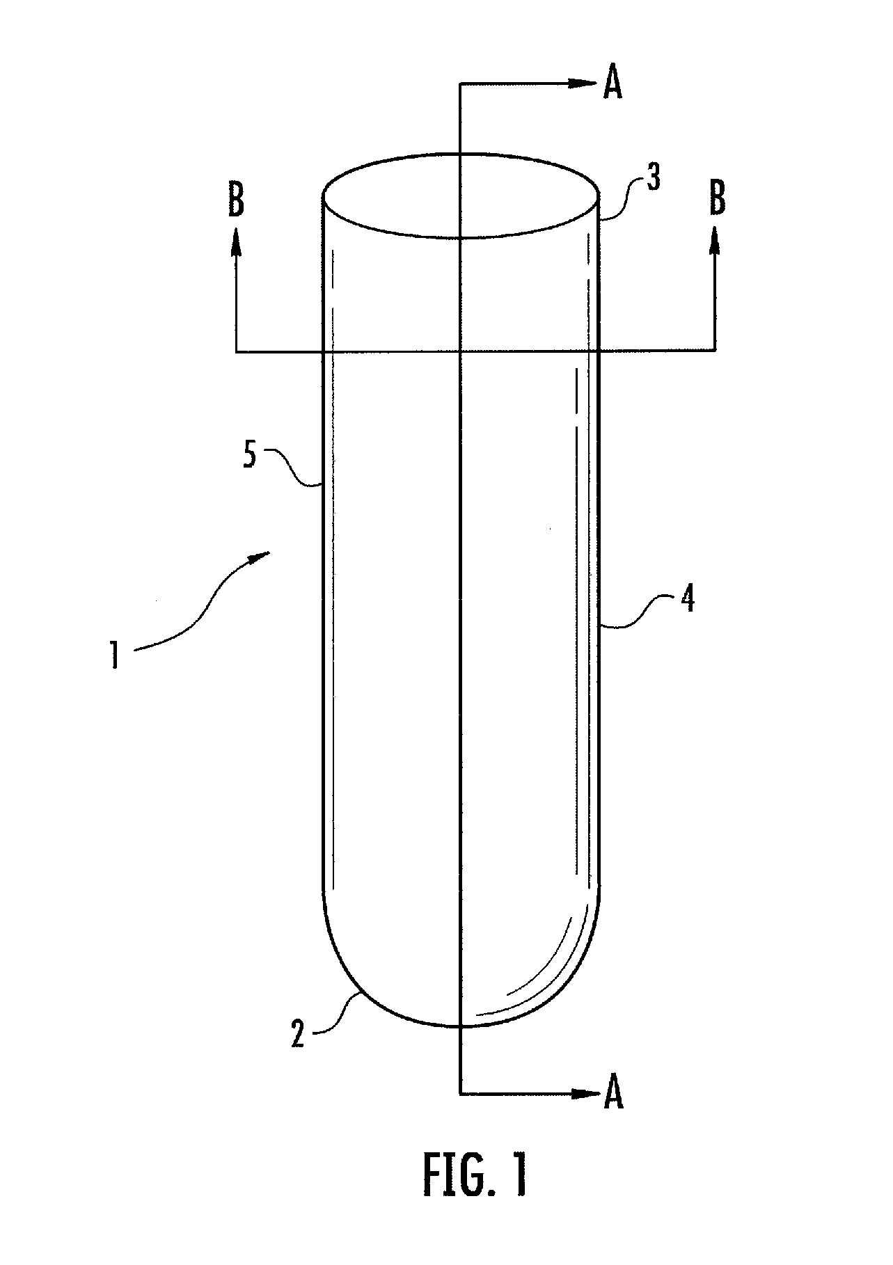
[0054]Referring to FIGS. 1-3, illustrated is a projectile 1 having a first leading end 2, referring generally to the end that makes contact with a target, and a second trailing end 3. The body of projectile 1 is further defined by side walls 4 and 5. A base plate 6 sealingly engages the projectile body adjacent to the second end 3, thus forming an inner portion 7. Although the figure illustrates a generally cylindrical shape body having a rounded front end, any shape is within the scope of the invention. Located within inner portion 7 is a plurality of ampoules 8 made of rupturable materials, such as glass or plastic, and which contain chemiluminescent reactant components.

[0055]Typical chemical light systems employ various chemiluminescent reactant components, including an oxalate ester, hydrogen peroxide, a fluorescer, and a catalyst. In its most basic form the two-component, liquid phase oxalate ester chemical light system must comprise an “oxalate component” comprising an oxalic ...


PUM


Abstract

The present invention relates to a non-pyrotechnic, self-illuminating projectile useful for marking, target illumination, or targeting adjustment which produces chemiluminescent light upon impact with an object. Because the production of light is delayed until impact, the projectile is not visualized until impact and the intensity of light upon impact is greater than light produced by projectiles that provide intermixing of light generating chemicals during flight.

Description

CROSS REFERENCE TO RELATED APPLICATIONS[0001]This application is a continuation-in-part (CIP) of U.S. application Ser. No. 12 / 526,274, which is a national stage filing in accordance with 35 U.S.C. §371 of PCT / EP2008 / 050599, filed Feb. 8, 2008, which claims the benefit of the priority of Belgium Patent Application No. 2007 / 0051, filed Feb. 8, 2007, the contents of each are incorporated herein by reference.FIELD OF THE INVENTION[0002]This invention relates to light emitting projectiles for marking an impact area, more particularly to a long range, long-flight time chemiluminescent projectile used for tactical and training exercises by military and law enforcement personnel which prevents light production resulting from forces associated with firing of the weapon, thereby retaining the amount of chemical light generated to occur as the projectile impacts the target area and releases its contents.BACKGROUND OF THE INVENTION[0003]Military and law enforcement personnel worldwide employ a ...

Claims


Application Information

Patent Timeline
Patent Type & Authority Applications(United States)
IPC IPC(8): F42B12/40F42B12/42
CPCF42B12/40
Inventor LADYJENSKY, JACQUESLONGO, JOSEPH COSIMOCRANOR, EARL
Owner CYALUME TECH
Learn More