Corona tip insulator

a technology of insulators and tip insulators, which is applied in the field of corona discharge ignitor, can solve the problems of insufficient durability to be practical for use in automotive and industrial engines, difficult processing of insulators of the desired geometry, and high cost of materials, and achieve the effect of increasing the electric field intensity

Active Publication Date: 2010-11-11
TENNECO INC
View PDF14 Cites 32 Cited by
  • Summary
  • Abstract
  • Description
  • Claims
  • Application Information

AI Technical Summary

Problems solved by technology

While BN has excellent dielectric breakdown strength and very low dielectric constant, both of which are highly desirable properties for the application, it is a very soft material, which makes it insufficiently durable to be practical for use in automotive and industrial engines.
It is also a very expensive material and is difficult to process into insulators of the desired geometry in an efficient manner for high volume manufacturing.

Method used


Image

  • Corona tip insulator
  • Corona tip insulator
  • Corona tip insulator

Examples


Embodiment Construction

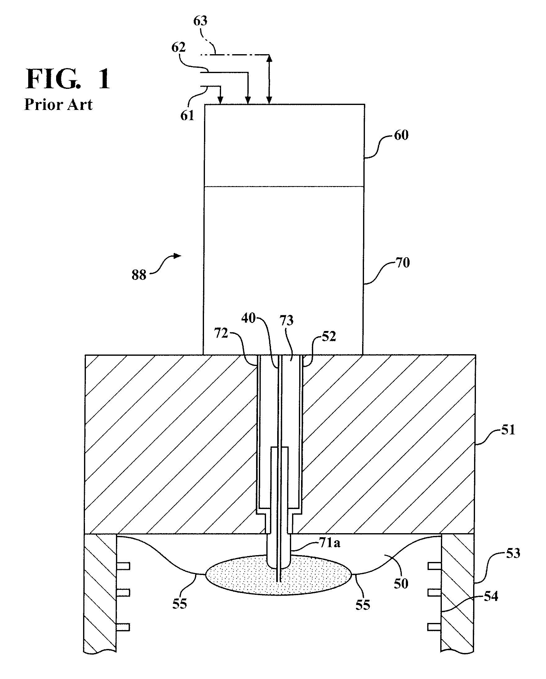
[0025]In a corona ignition system, a radio frequency signal is generated in an electronic circuit and transmitted through a coaxial cable to an ignitor. If the voltage is too high, then an unwanted arc can form from the electrode tip to the head. Typically, prevention of arcing is accomplished using either a circuit to detect and stop the arc, or a mechanical barrier is placed around the electrode. However, the barrier serves to reduce the electric field intensity which is required to achieve ignition. The instant invention serves to provide an electric field intensity which is great enough to achieve ignition, without arcing or the requirement to detect such arcing.

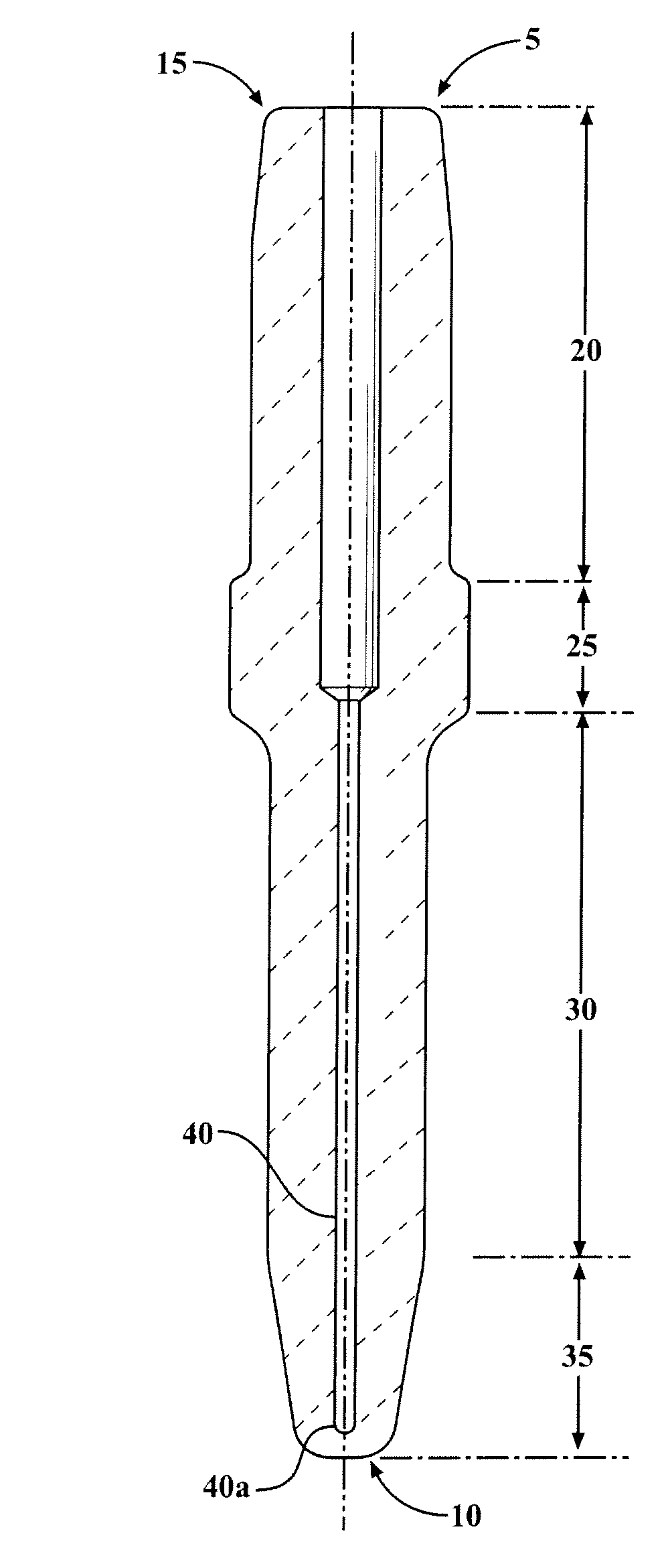
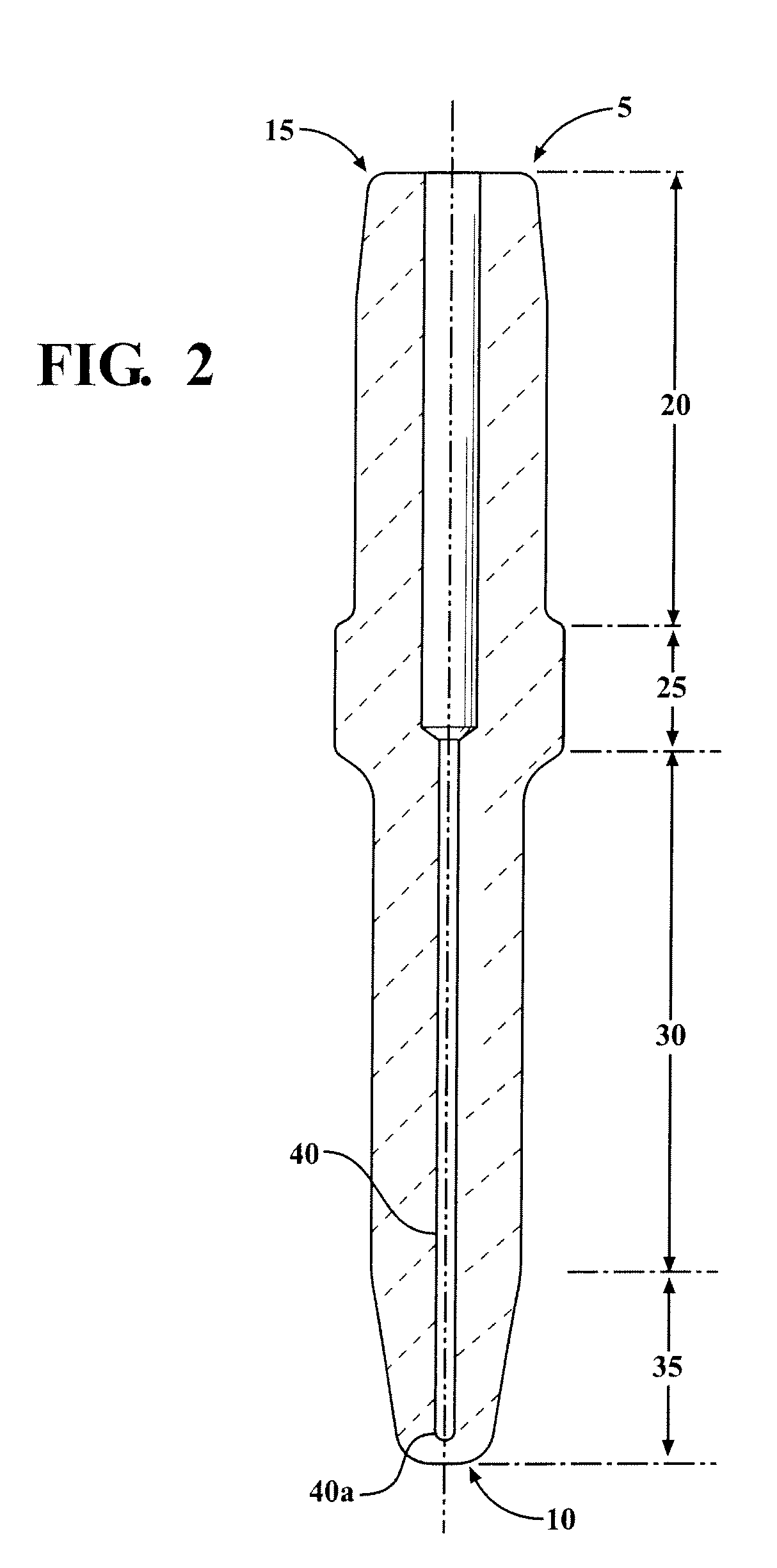
[0026]As illustrated in FIG. 2, an insulator 5, typically made of ceramic and non-conducting, extends between a corona forming end 10 and a terminal end 15. From the terminal end 15 and extending toward the corona forming end 10, the corona forming end assembly insulator 5 includes a terminal portion 20, a large shoulder...


PUM

PropertyMeasurementUnit
electric field intensityaaaaaaaaaa
conductiveaaaaaaaaaa
dielectricaaaaaaaaaa

Abstract

This invention relates to a corona discharge ignitor used to ignite air / fuel mixtures in automotive applications and the like. To suppress an arc from forming when a voltage is applied to the ignitor, the corona discharge ignitor has various shapes and configurations, such as angular depressions or grooves, at the tip of the insulator. The shape and configuration of the tip provides a smaller radius which creates a more intensified electric field and provides better combustion.

Description

CLAIM FOR PRIORITY[0001]This application claims the benefit of priority to U.S. provisional application 61 / 175,111, filed May 4, 2009, the contents of which are hereby incorporated by reference.TECHNICAL FIELD[0002]This invention relates generally to a corona discharge ignitor used to ignite air / fuel mixtures in automotive applications and the like, and in particular to a corona discharge ignitor having angular depressions or grooves at the tip of the insulator.RELATED ART[0003]Conventional spark plugs generally utilize a ceramic insulator which is partially disposed within a metal shell and extends axially toward a terminal end. A conductive terminal is disposed within a central bore at the terminal end, where the conductive terminal is part of a center electrode assembly disposed within the central bore. At the opposite / corona forming end, the center electrode is disposed within the insulator and has an exposed sparking surface which together with a ground electrode disposed on th...

Claims


Application Information

Patent Timeline
Patent Type & Authority Applications(United States)
IPC IPC(8): F02B19/00H01S4/00
CPCY10T29/49002H01T19/04H01T13/50
Inventor PERMUY, ALFREDHAMPTON, KEITH
Owner TENNECO INC
Why Eureka
Try Eureka